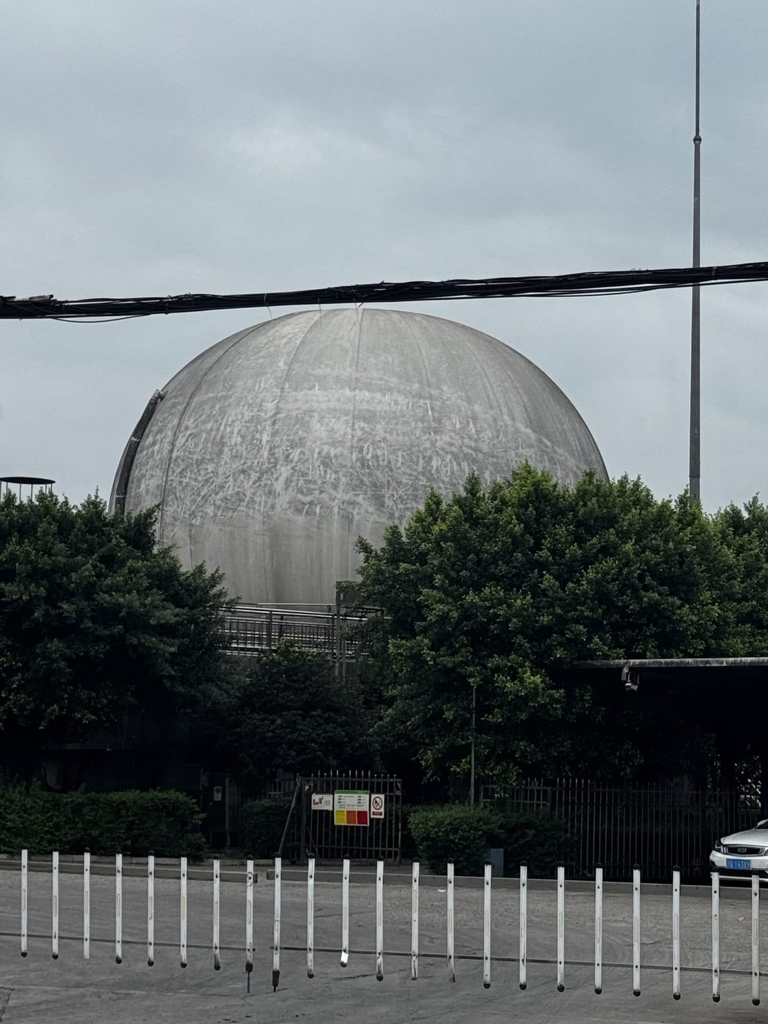
Part 1 ended with the failed inner membrane removed and the base membrane, anchor channel, clamping hardware and interfaces exposed. Part 2 is not simply about putting a new membrane back; it is about rebuilding a continuous, inspectable and verifiable sealing and load-transfer system.
Review inner-membrane replacement Part 1Installation and acceptance chain
- 01Base released
- 02Lower seal
- 03Inner membrane
- 04Upper seal
- 05Outer reinstated
- 06Instrumentation
- 07Staged inflation
- 08Leak acceptance
Safety and scope
This article explains sequence and quality control; it does not replace a site-specific method statement, permit to work, gas testing, energy isolation, lifting plan or local law. EPA AgSTAR treats inspection, maintenance, records and safety as core biogas-system practices, while OSHA 1910.147 requires control and verification of hazardous-energy isolation before maintenance. Approved project documents and local requirements govern the work.
1. Base Release and the First Continuous Sealing Strip
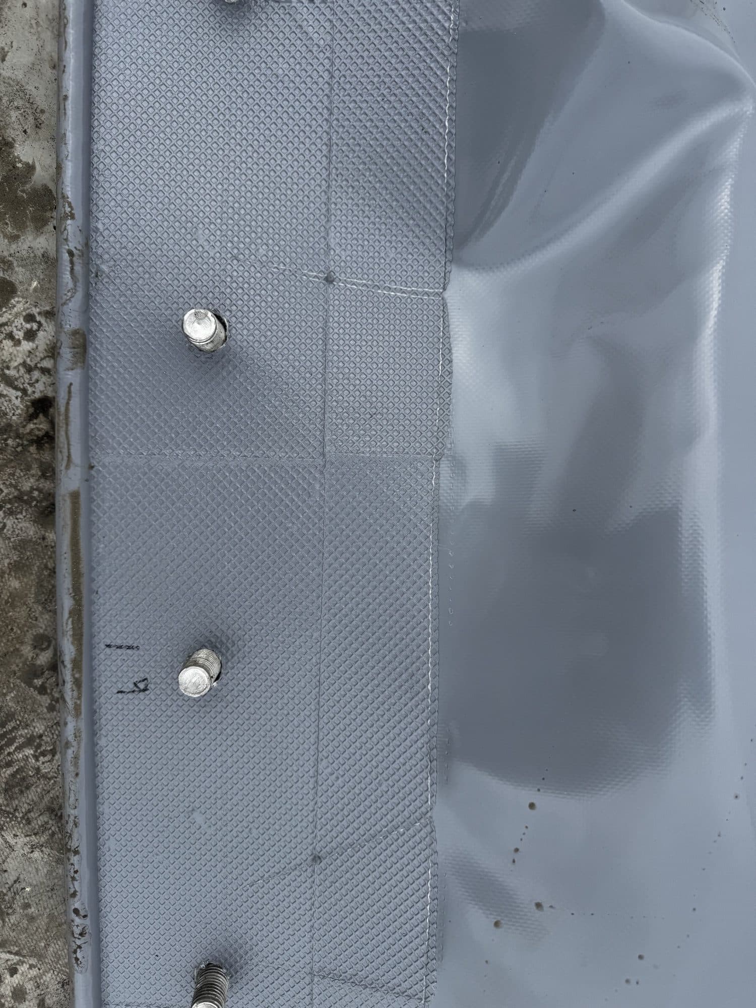
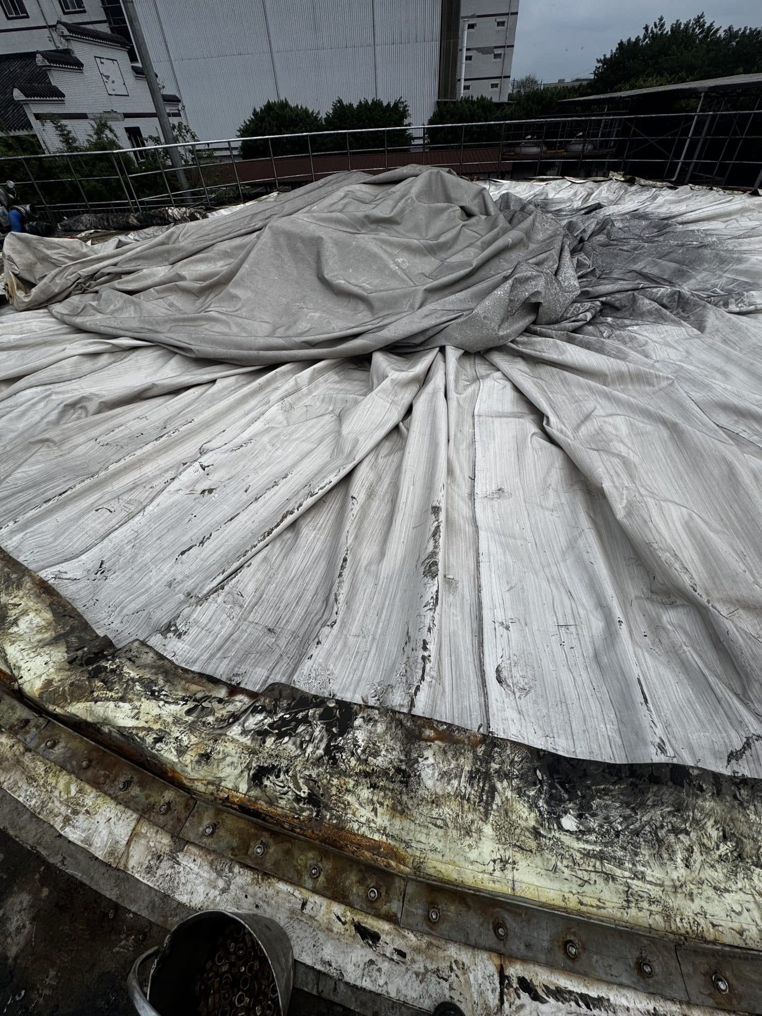
Before the new membrane enters the work area, the base membrane, foundation edge, anchor channel, flange faces and studs should be released as a hold point. Remove hard residue and standing liquid, eliminate sharp edges and verify the flatness and continuity of reusable clamping parts. The first continuous sealing strip is installed only after this interface is accepted.
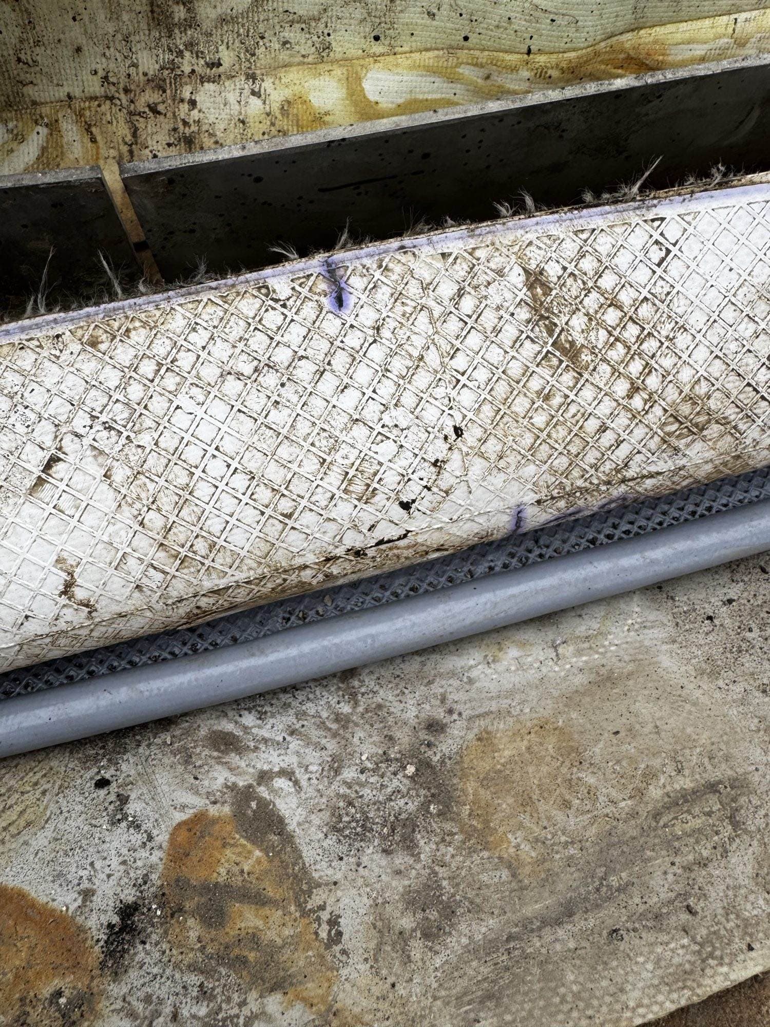
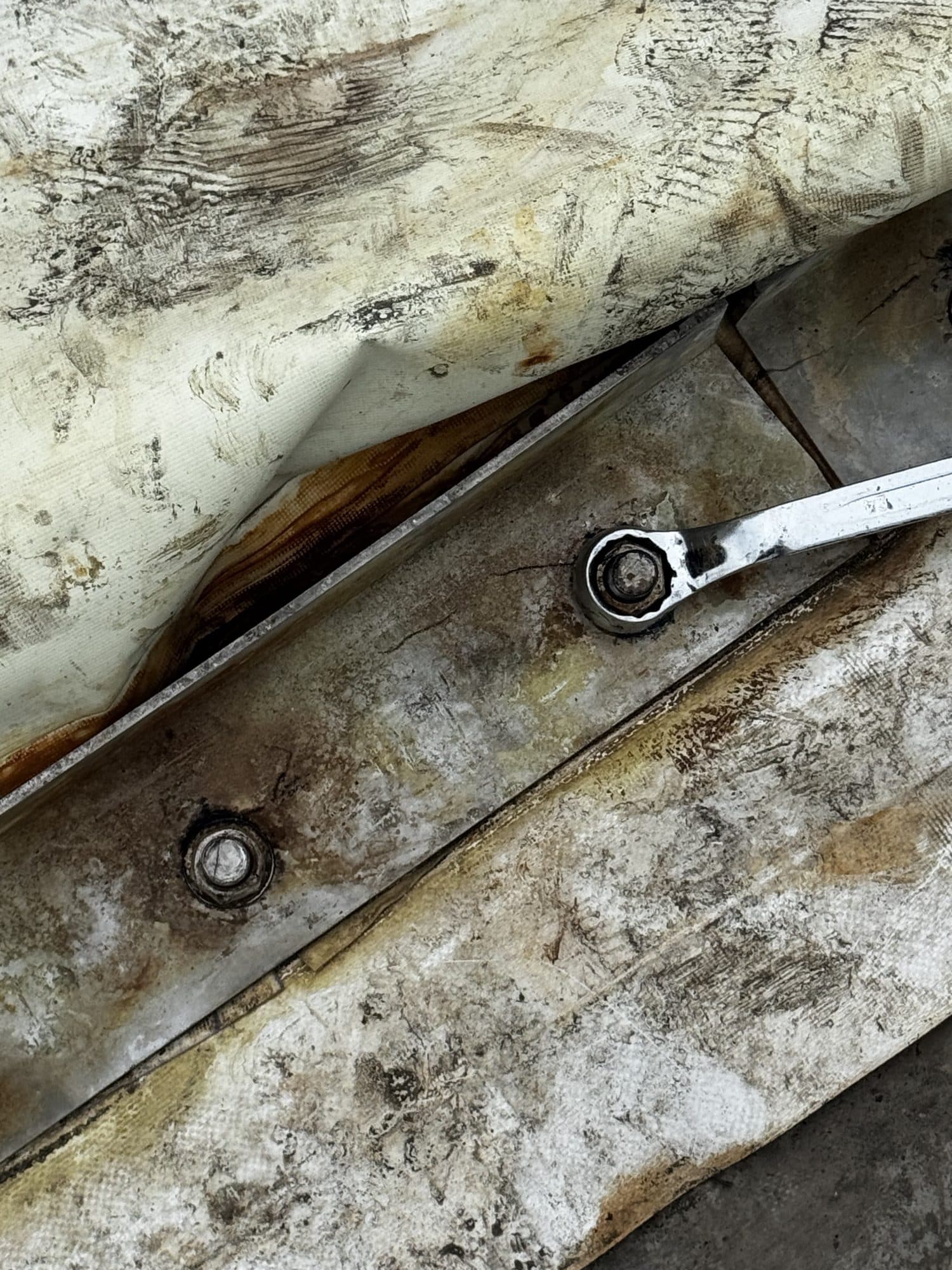
The strip is not an improvised gap filler; it is part of the compression seal. Corners, overlaps, holes and joints must remain continuous and traceable. Material, profile, jointing method and target compression follow the approved drawings and supplier documentation.
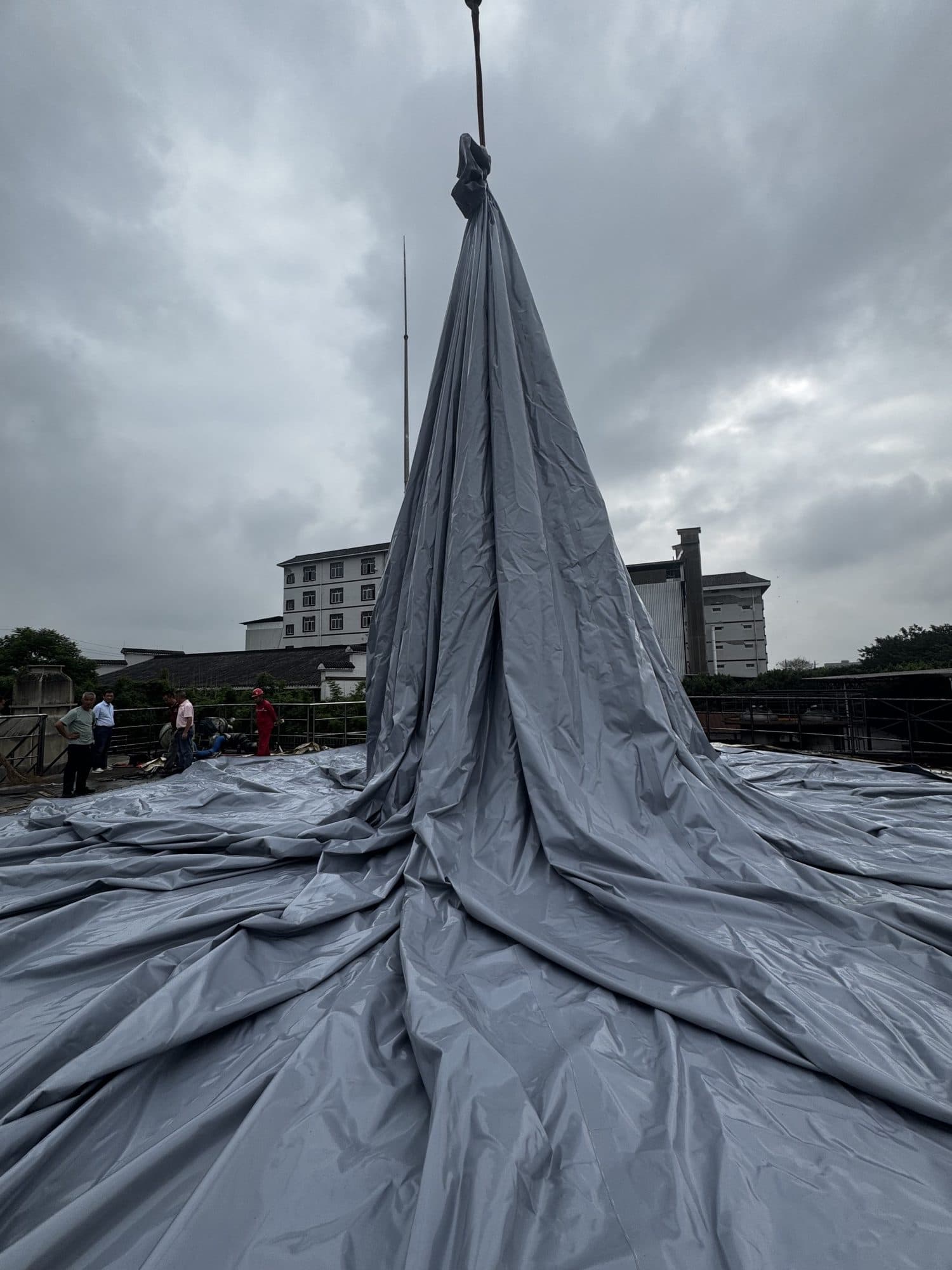
2. Lift, Orient and Unfold the New Inner Membrane
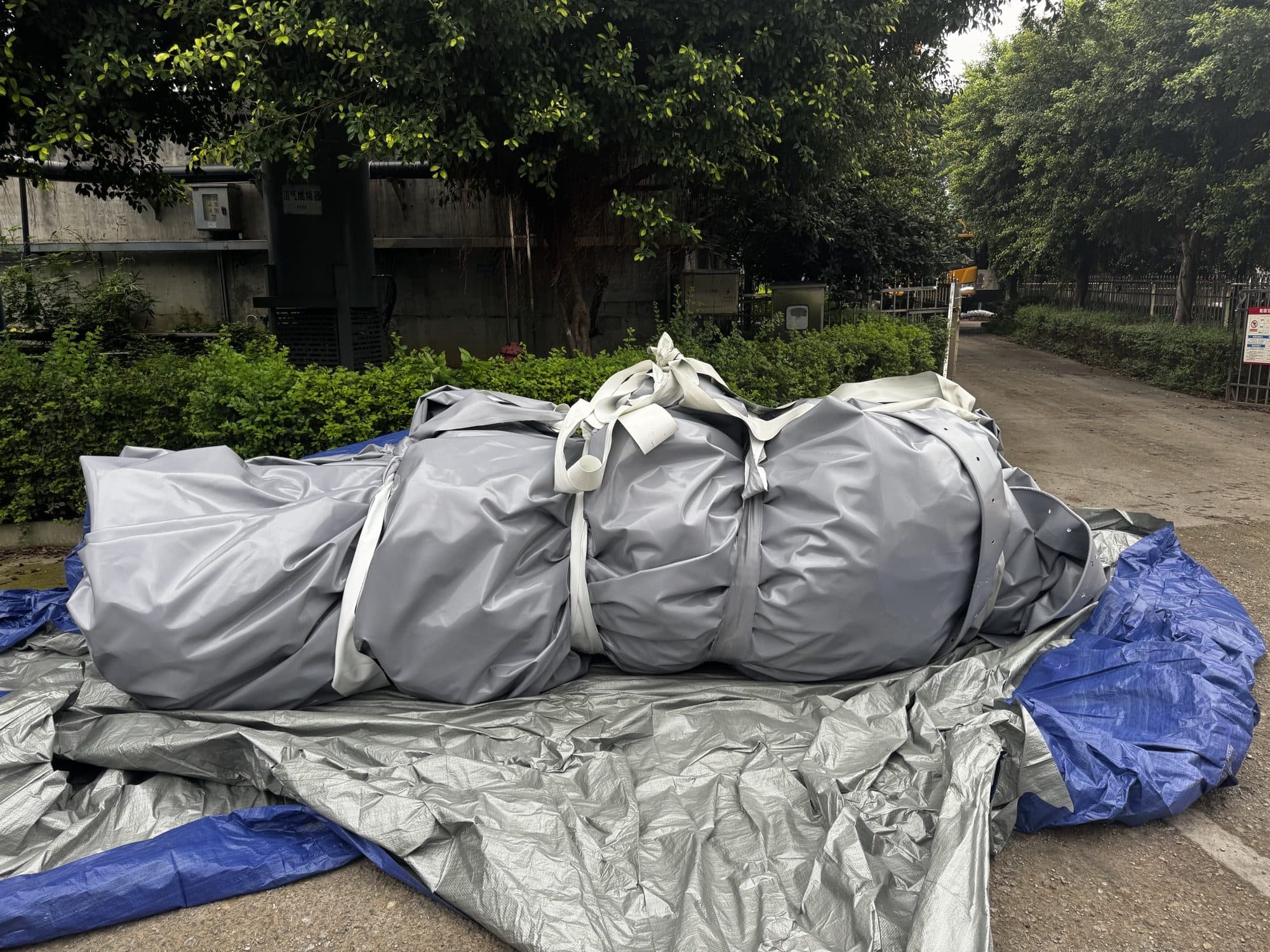
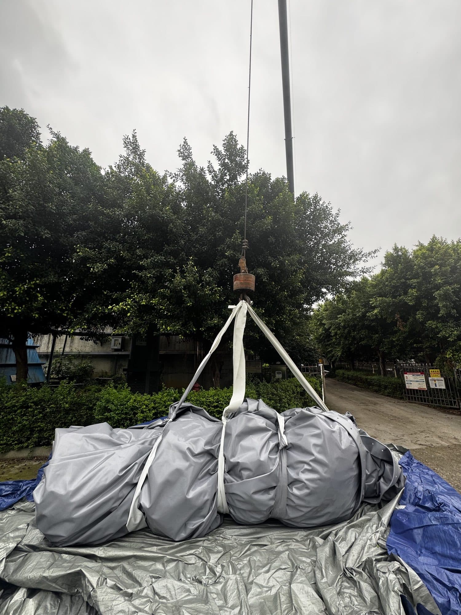
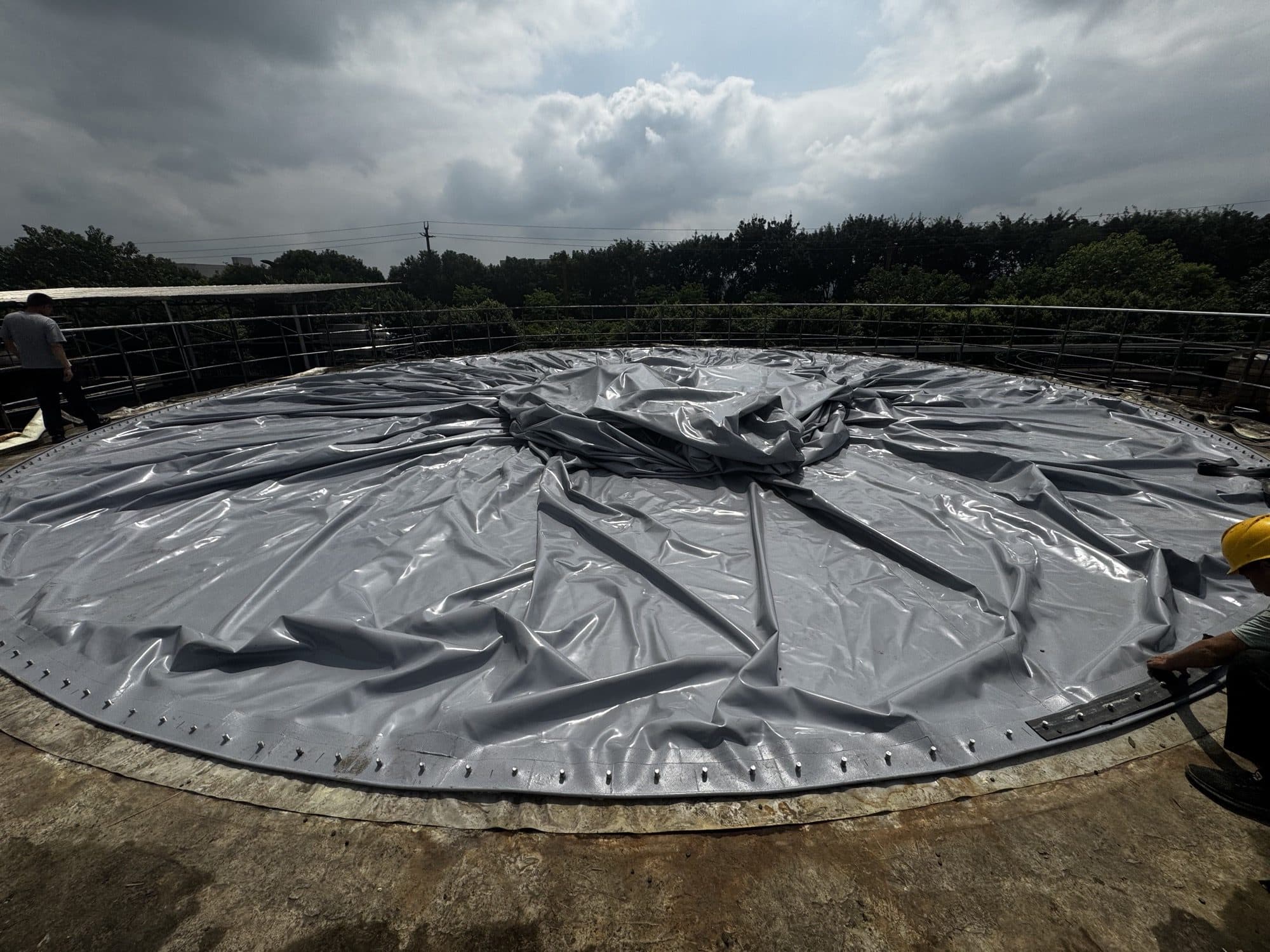
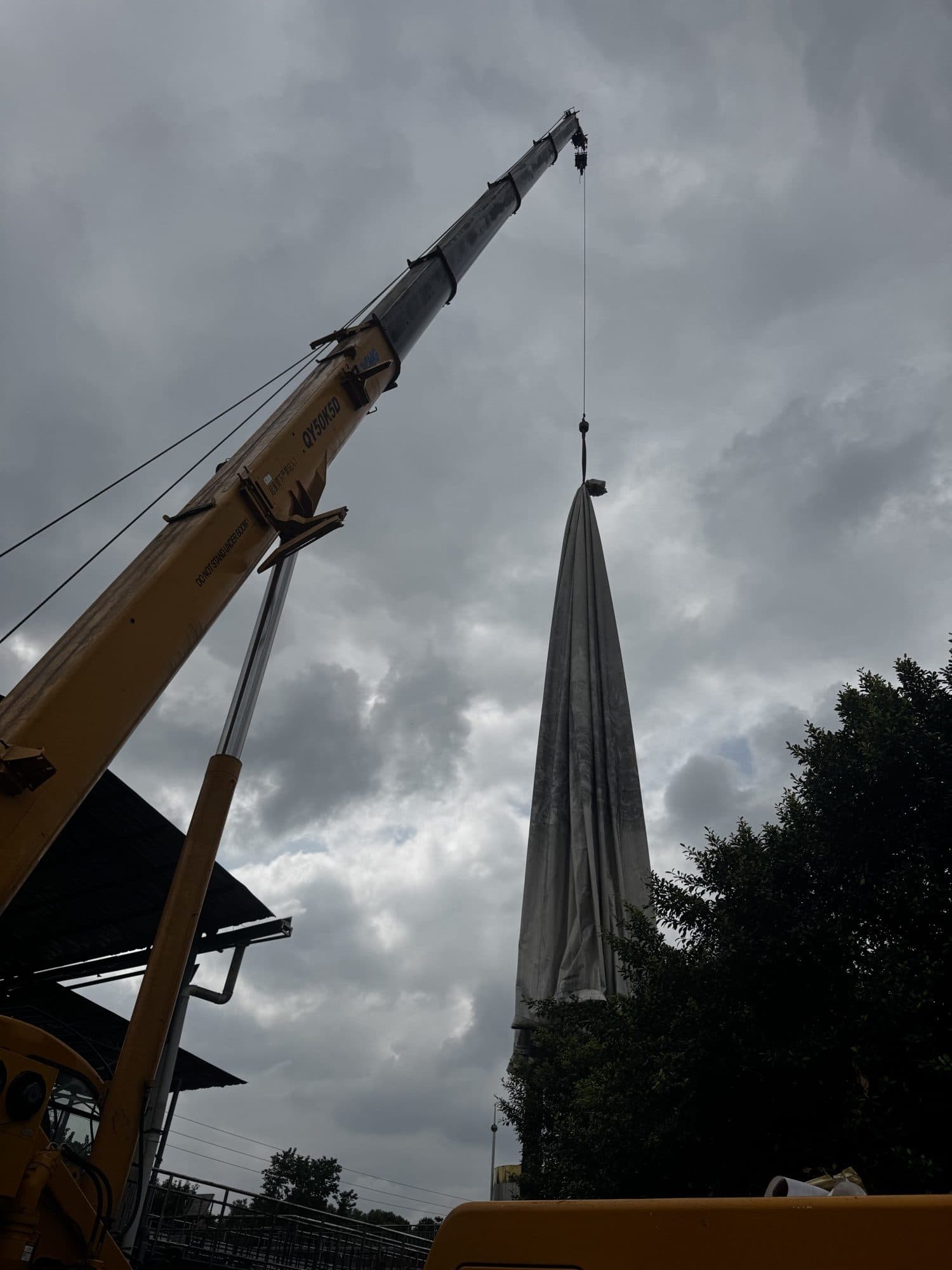
Before lifting, verify the membrane centre, interface orientation, installation datum and sling condition. The lifting arrangement controls the unfolding path; no single fitting, weld or perimeter flange should carry the full load. Lower the bundle slowly under ground guidance to avoid rails, studs and sharp steelwork.
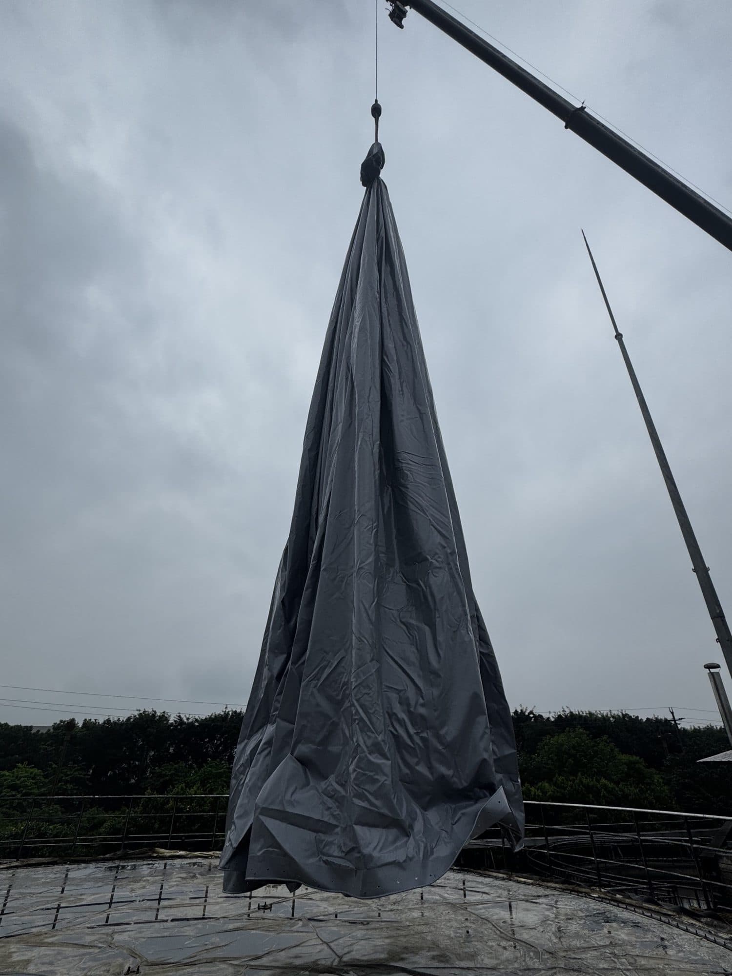
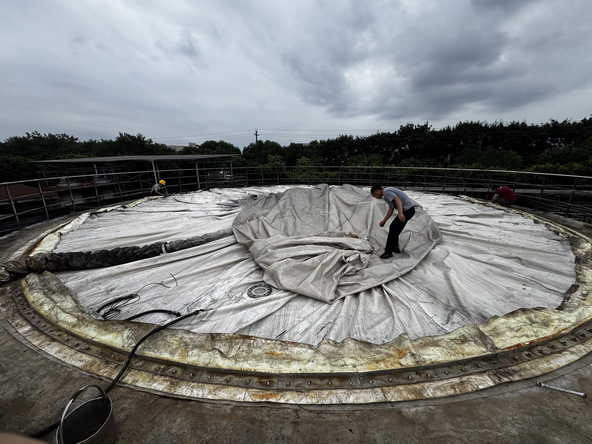
Establish the centre and primary interface orientation before releasing each folded zone. Personnel stay on suitable walk areas and move the membrane with soft handling points, keeping footwear, tools and drag loads away from welds and fitting roots.
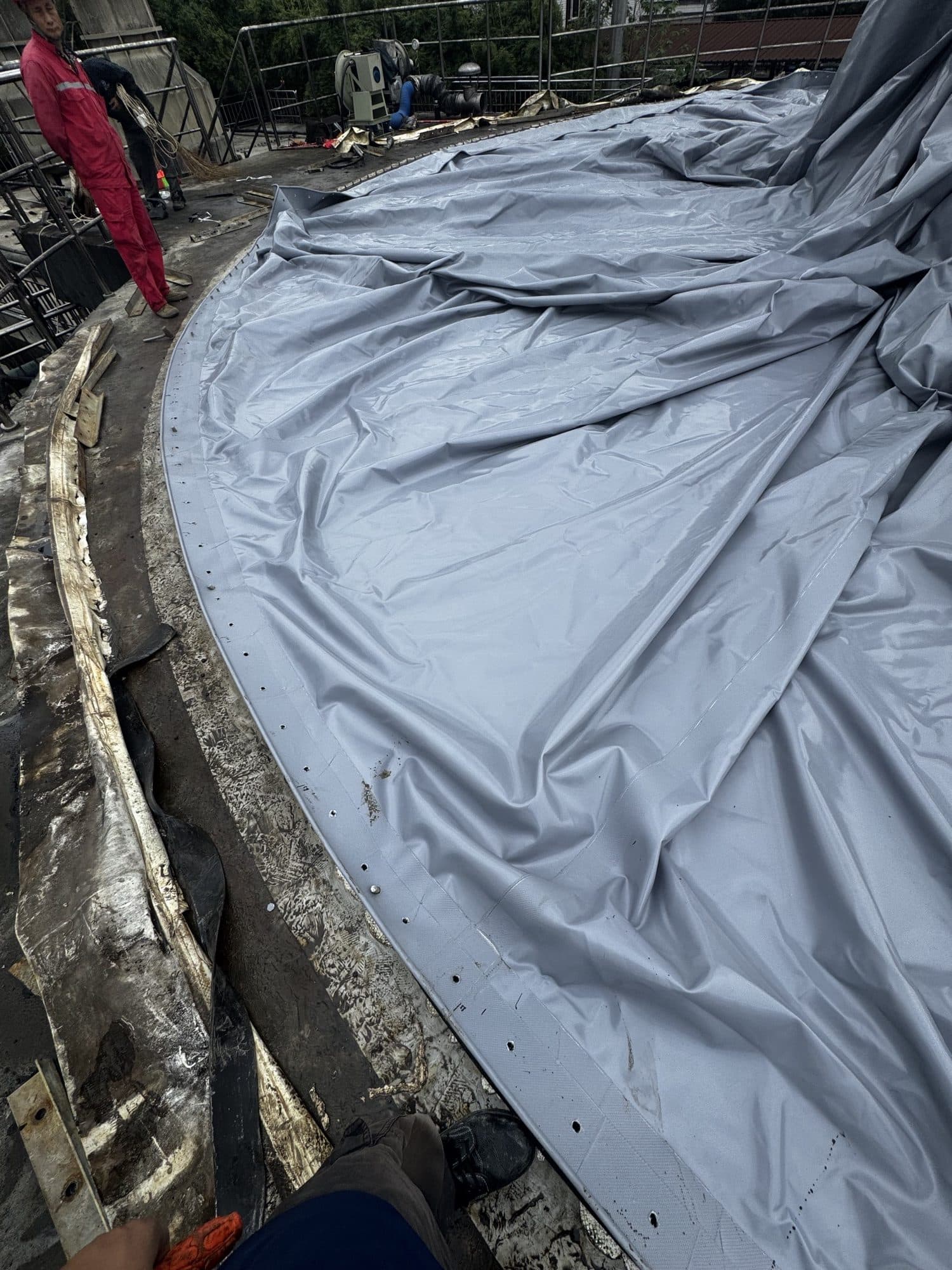
3. Perimeter Alignment, the Second Seal and Staged Clamping
After the reinforced perimeter lands on the lower strip, verify orientation and hole positions from defined datums, then work in opposing sectors. Marking and hole checks establish the actual geometry; they do not mean tightening each visible hole immediately. If error accumulates, return to centring and membrane lay rather than forcing the edge.
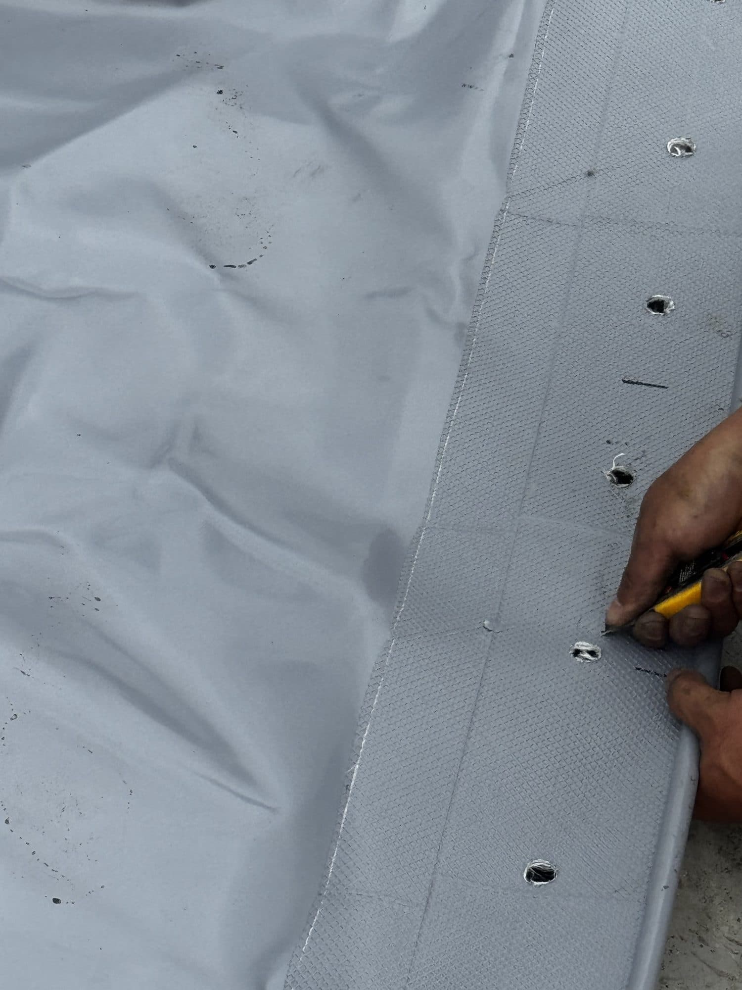
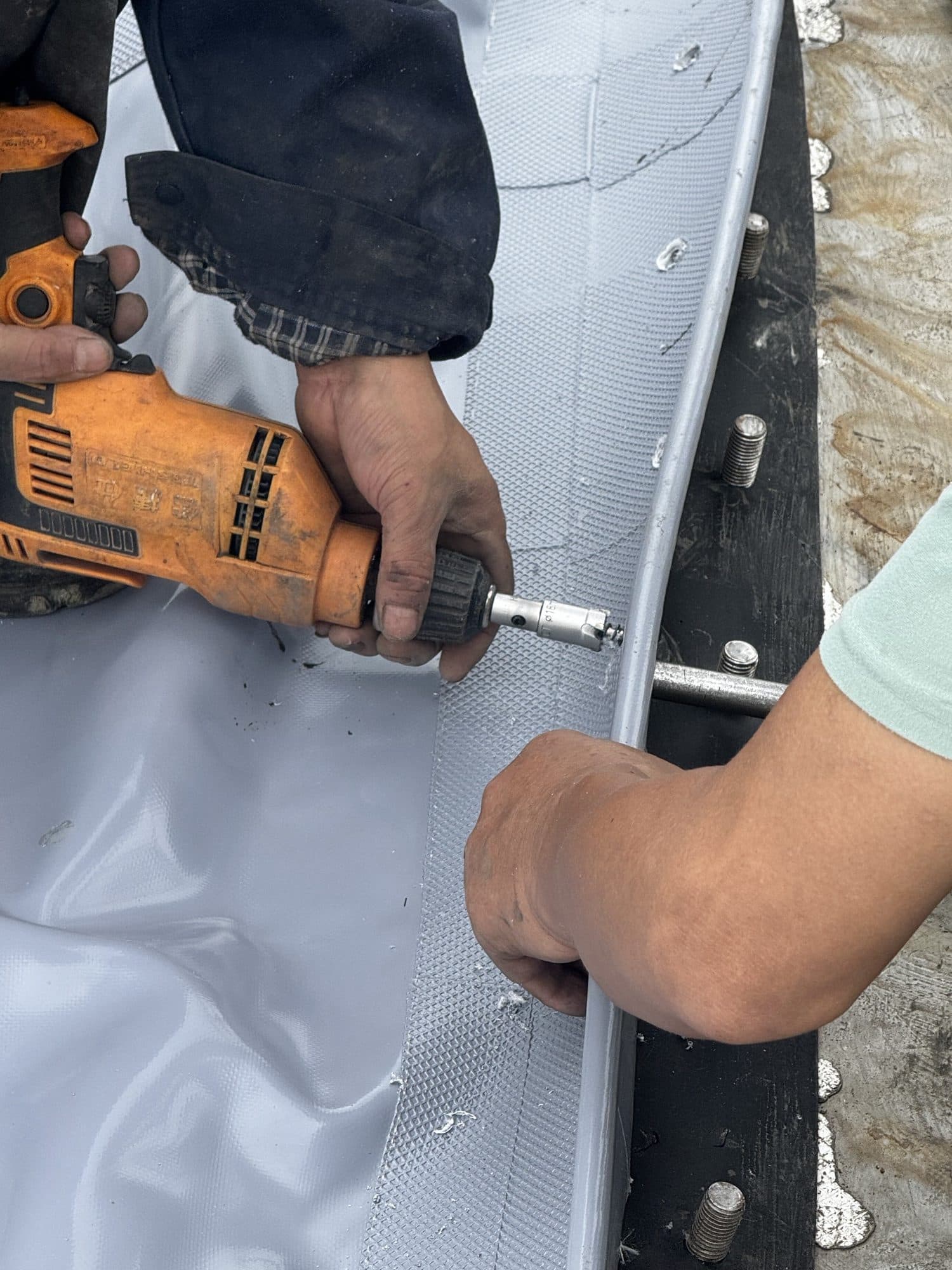
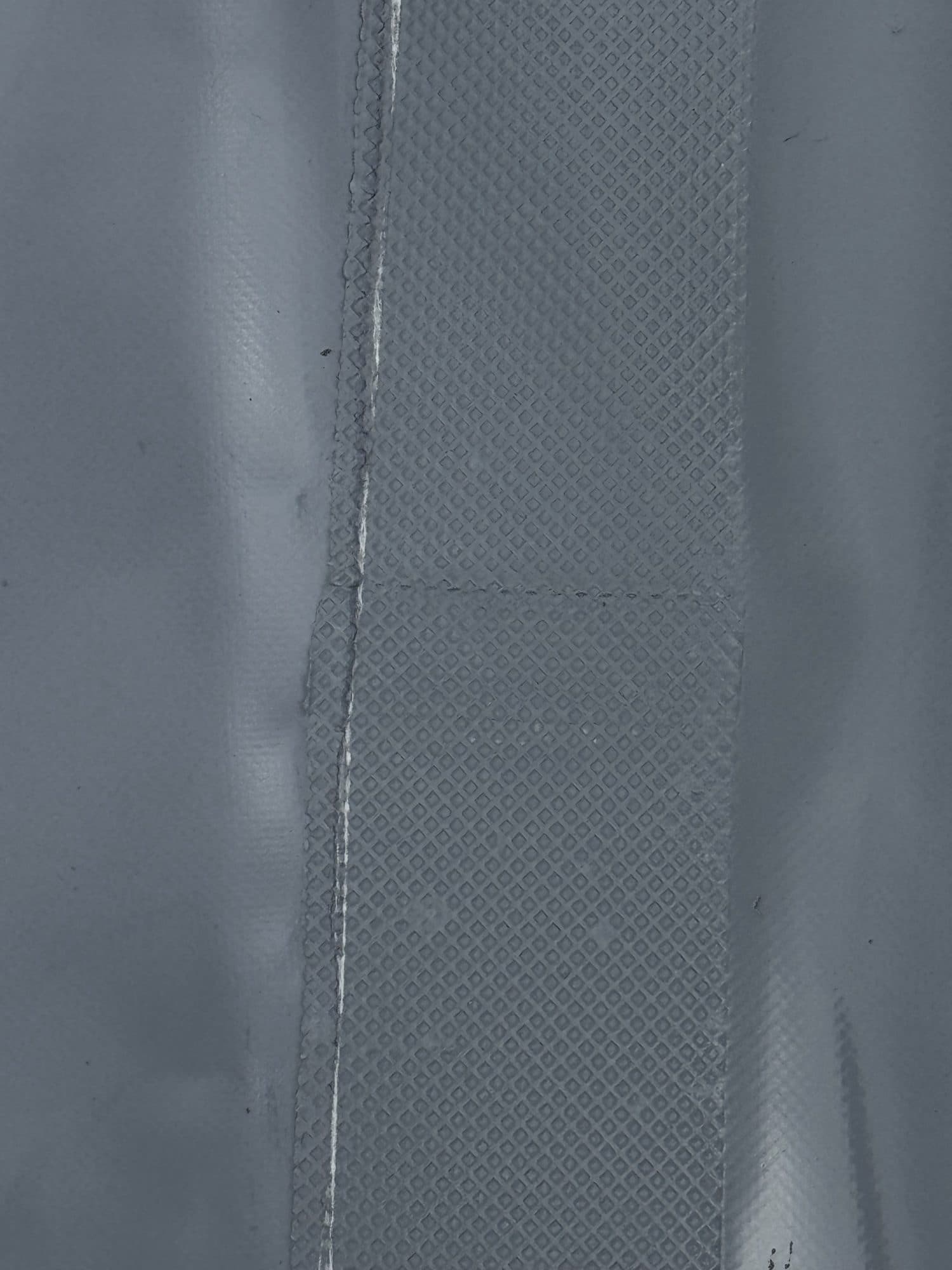
After the inner membrane passes its hold point, the second continuous sealing strip is placed above it before the retained outer membrane is reinstated. This creates an auditable stack—support surface, lower strip, new inner membrane, upper strip, retained outer membrane and clamping hardware—subject to the approved project drawings.
4. Reinstate the Retained Outer Membrane in Its Original Orientation
The retained outer membrane lifted in Part 1 is returned only after the new inner membrane and upper sealing strip pass inspection. Original orientation marks, fitting direction and lifting points are checked, while ground guidance controls folds and prevents contact with rails, sharp edges and the new inner membrane.
5. Restore Penetrations, Level Signals and Wiring
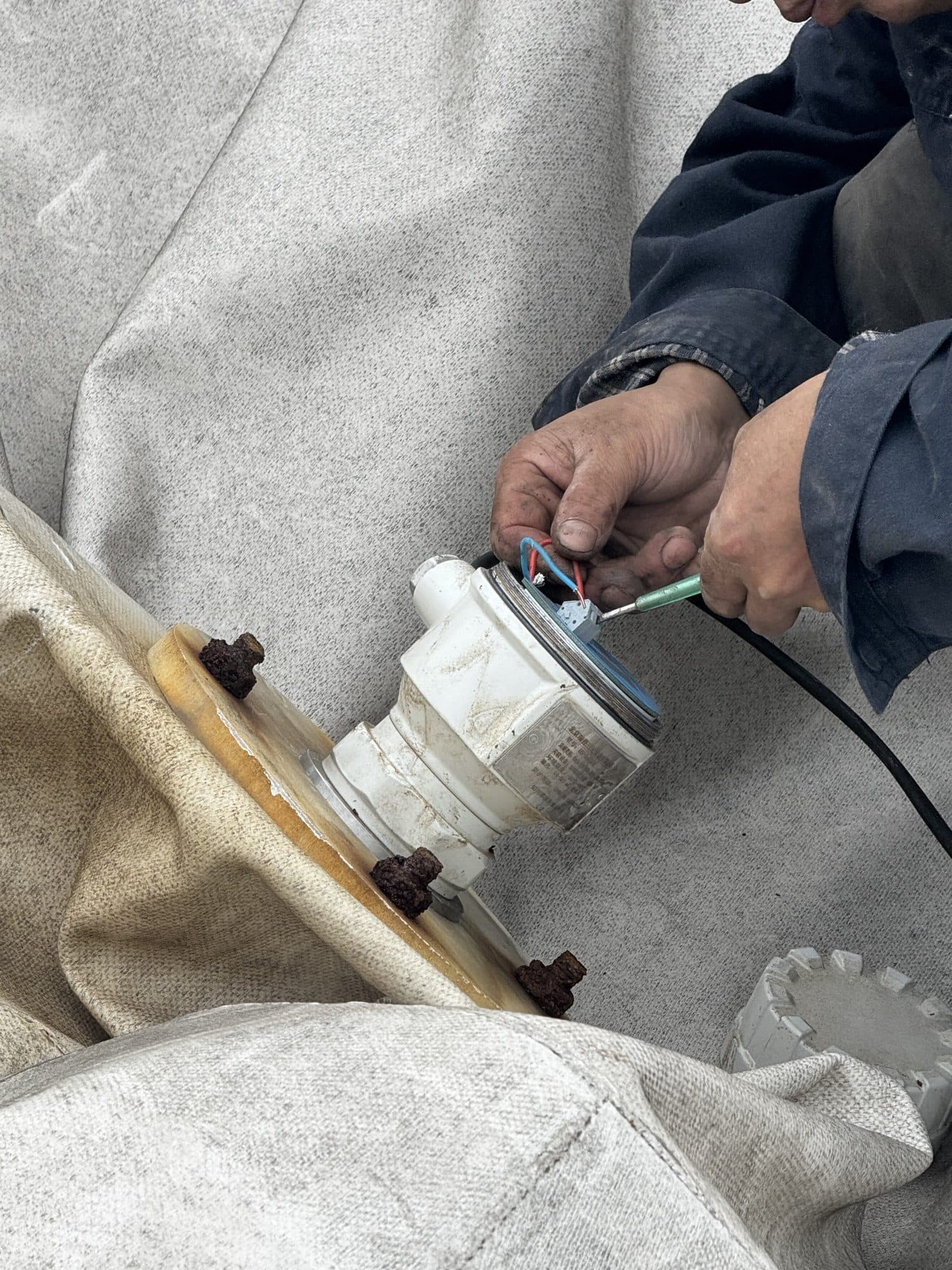
After clamping, restore the level instrument, pressure tapping, air duct and cables using the removal records. Reconnection is more than joining wires: verify terminals, polarity or signal definition, strain relief, sealed glands, flange fastening and water-shedding path, then complete the loop check.
6. Staged Inflation: Form, Observe and Verify
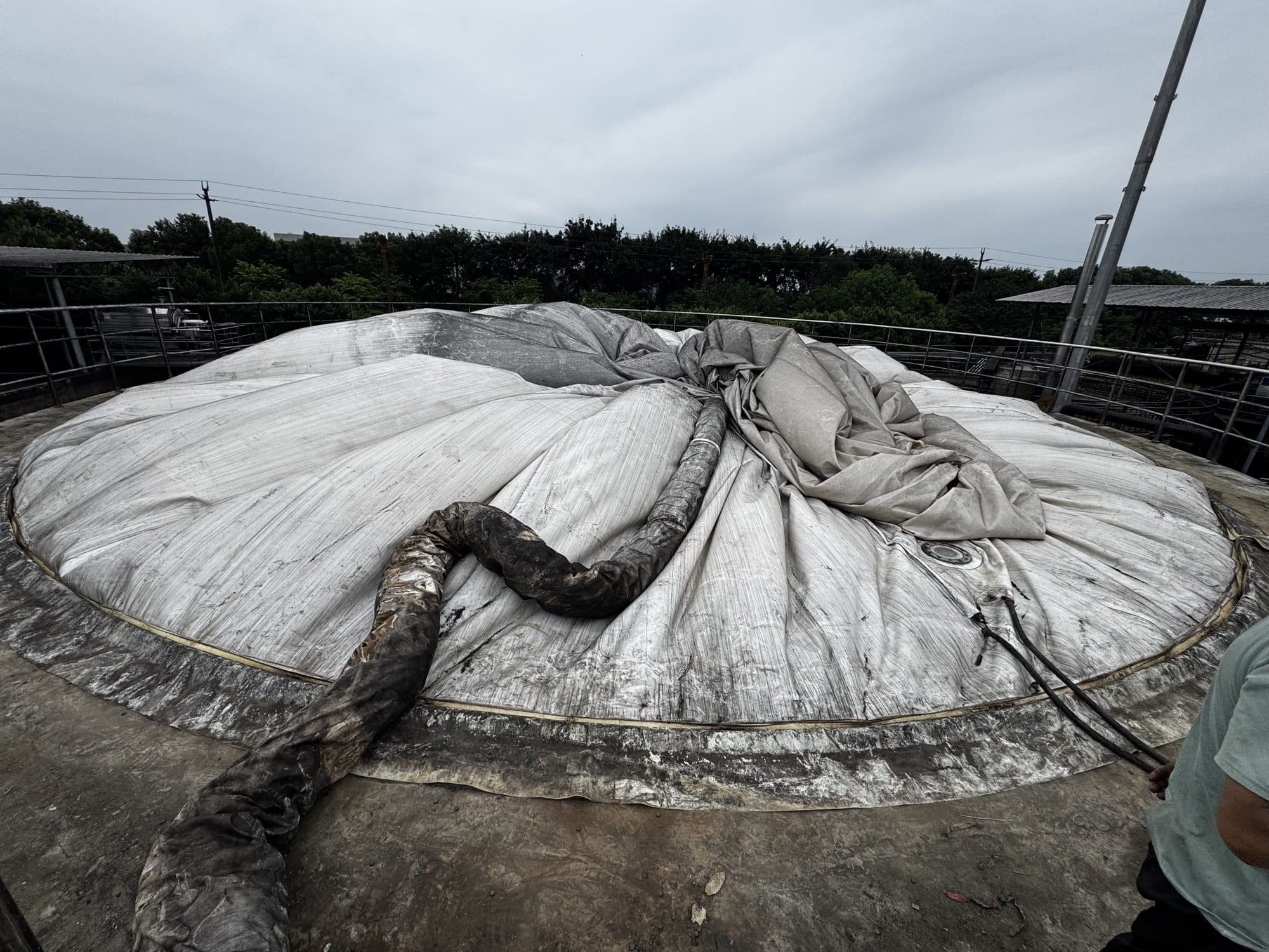
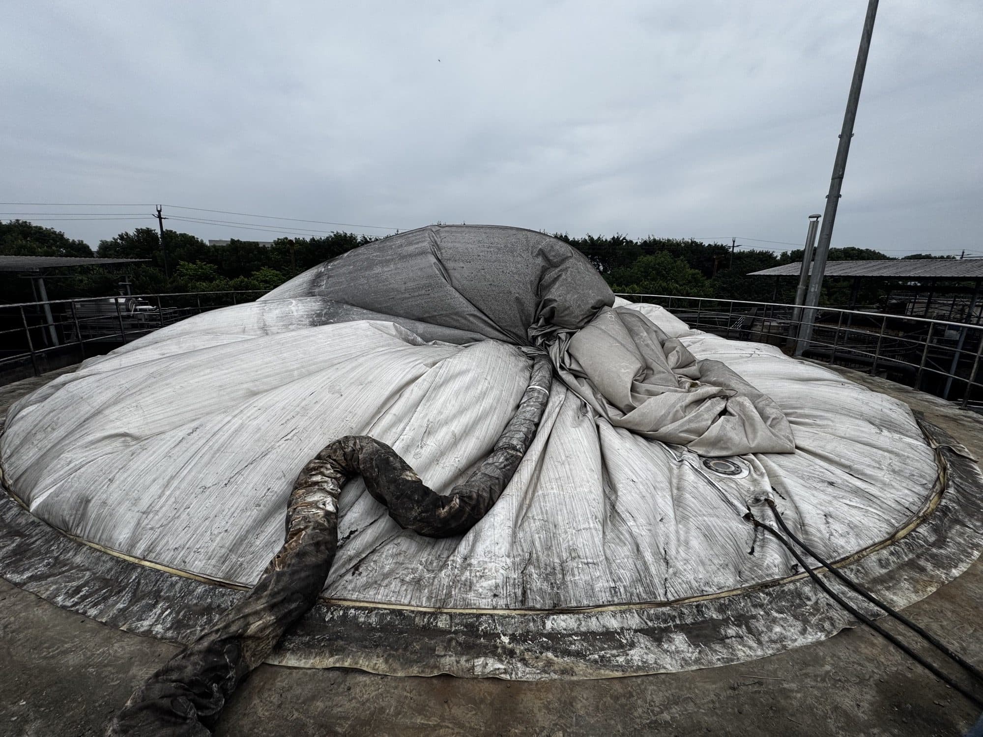
First inflation must be a controlled process that can be stopped at any time. Establish support air and allow the outer membrane to form gradually while inspecting the perimeter clamp line, air duct, fittings and wrinkle migration. Stop for abnormal rubbing, local tension, fitting movement or implausible pressure and level signals.
7. Foam-Solution Leak Checks, Functional Tests and Final Acceptance
Once the membrane form is stable, apply a membrane-compatible foam leak-detection solution to accessible flanges, penetrations, pressure taps and other approved test points. Persistent bubble growth indicates a possible leak that must be marked, depressurised, corrected and retested. The absence of audible leakage is not acceptance evidence.
Then verify support-blower changeover, pressure and level signals, alarms and interlocks, recording shape and operating trends under the project-defined condition. Test medium, pressure, stabilisation time and acceptance criteria come from the approved procedure; this article does not substitute generic values.
Six common errors
- Covering hard debris, standing liquid or sharp edges with the new membrane.
- Allowing the sealing strip to break at corners, overlap unpredictably or be cut by bolt holes.
- Forcing hole alignment from one point and transferring wrinkles and eccentricity around the circumference.
- Fully tightening a local group of bolts instead of using a symmetric staged sequence.
- Dragging the retained outer membrane over sharp edges or allowing lifting gear to crush it.
- Accepting a rounded final shape without verifying signals, alarms, interlocks and leakage records.
Final acceptance record
- Lower and upper sealing strips are continuous, compatible and follow a clear compression path
- Inner-membrane orientation, centre and perimeter hole alignment are recorded
- Pressure bars, fasteners and tightening sequence follow the approved documents
- Inner-membrane seams, flange edge and penetrations pass visual inspection
- The retained outer membrane has no new abrasion, trapped folds or hard contact
- Blower, pressure, level, alarm and interlock signals are checked
- Membrane form remains stable without abnormal rubbing during staged inflation
- Accessible interfaces pass documented foam-solution leak checks
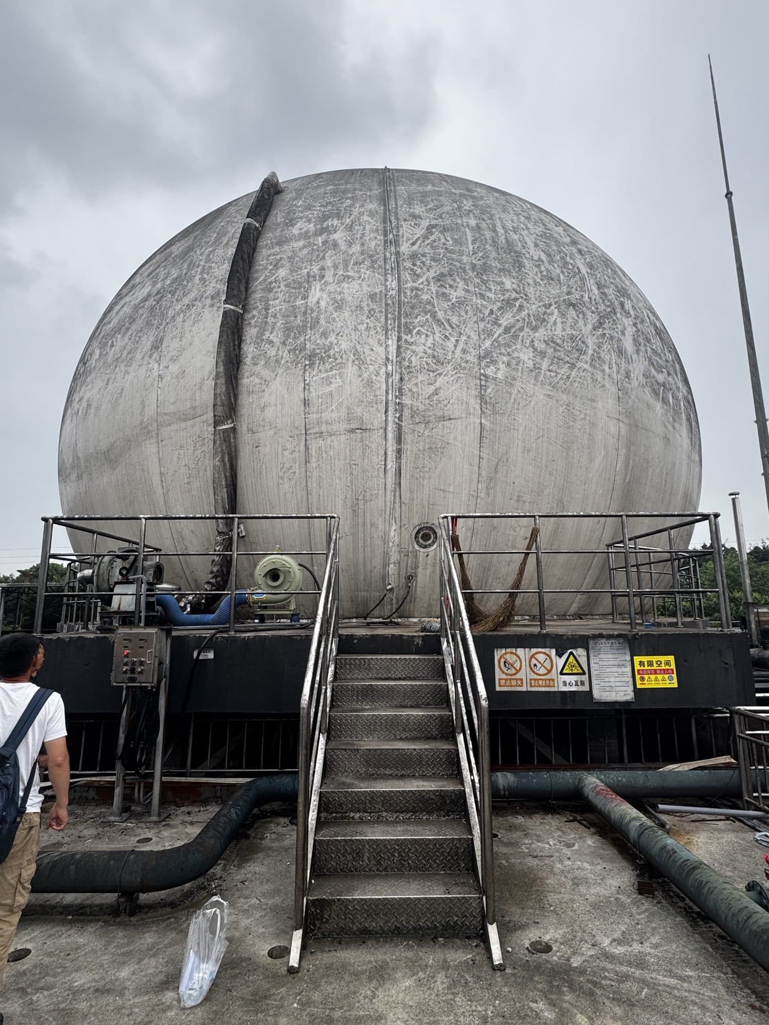
Professional handover is not defined by “the holder inflated.” Every interface hidden by the next layer must have been inspected, recorded and released, with final form, leakage results and control signals supporting the same conclusion.
Frequently Asked Questions
Why are sealing strips installed on both sides of the membrane flange?
The lower and upper continuous strips create controlled compression interfaces between the support surface, membrane flange and retained outer membrane. Their material, section and compression must follow the approved design.
Can misaligned bolt holes be pulled into position from one point?
No. The membrane should be centred and aligned progressively around the circumference. Forcing one local point can transfer wrinkles and stress into the membrane, welds and penetrations.
Can the retained outer membrane be reinstalled immediately after the inner membrane is fixed?
Only after the inner membrane, seams, flange, sealing strip, penetrations and clamping sequence have passed the defined hold-point inspection.
What should be checked while the gas holder is inflated?
Observe membrane shape, wrinkle migration, contact with nearby steelwork, blower response, pressure and level signals, alarms and interlocks throughout staged inflation.
How is foam solution used during leak checking?
Apply an approved compatible solution to accessible test points under the specified test condition. Persistent bubble growth indicates a possible leak that must be corrected and retested.
Does a normal final shape prove the replacement is complete?
No. Final acceptance also requires documented sealing, fastening, instrumentation, alarm/interlock, leakage and operating checks under the project procedure.
Inner-membrane replacement and acceptance inquiry
Turn every hidden interface into verifiable engineering evidence.
Share the gas-holder arrangement, dimensions, gas service, failure photographs, shutdown window and control information. MOTET can define the replacement, sealing review, reinstatement and acceptance scope.