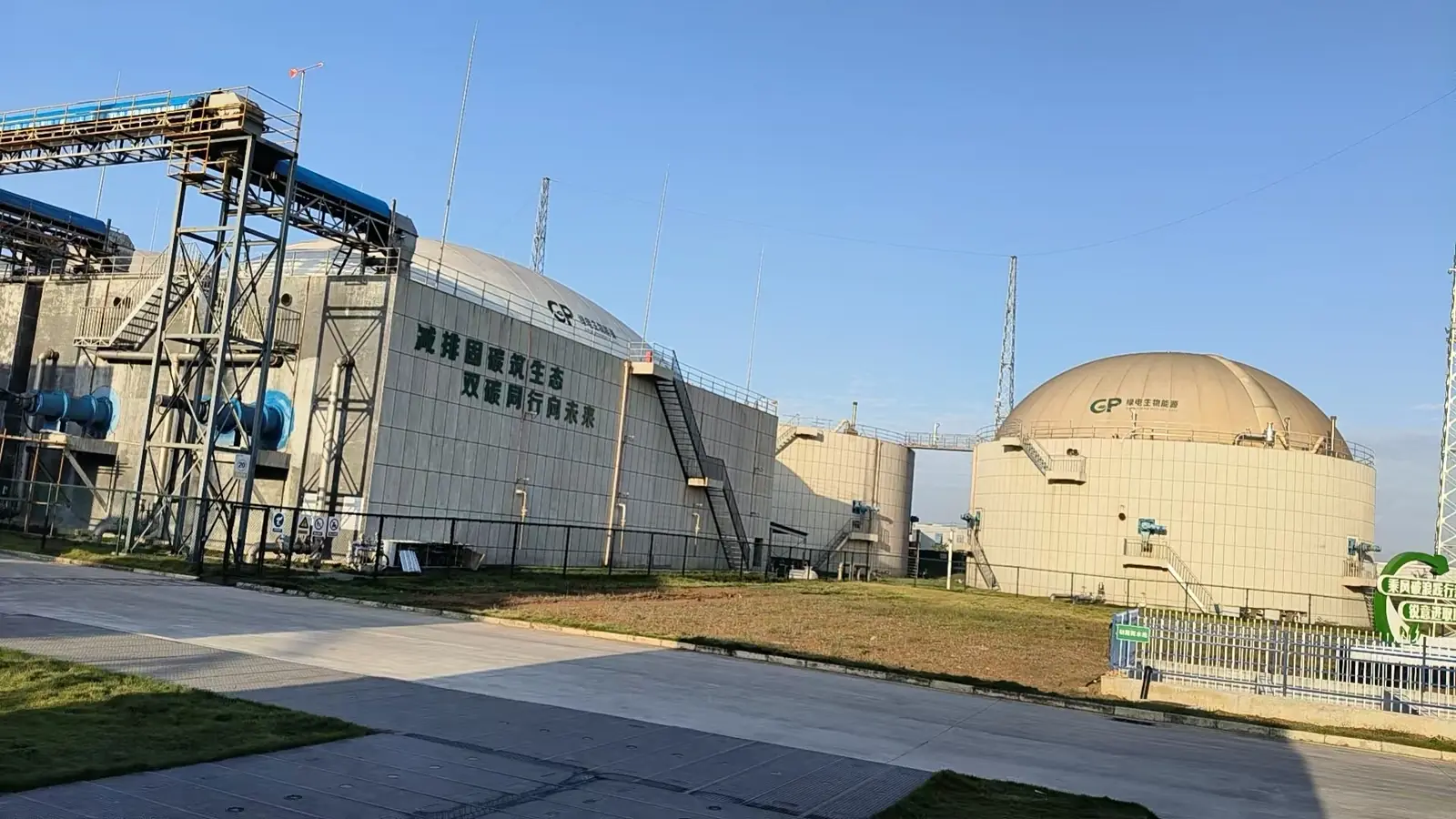
This Anhui project involved local repair of the existing membrane followed by reinstallation, not replacement of the complete inner and outer membranes. The equipment is a tank-top double membrane gasholder, with the gas storage enclosure mounted above the tank. These 29 site photographs document the gasholder membrane, crown plate, clamps and sealing interfaces, together with lifting, tank-top spreading and reinstallation details.
Scope and safety
This is a field record, not a do-it-yourself repair or reinstallation manual. Work involving biogas equipment, tank-top access and lifting requires competent personnel, equipment documentation, a site risk assessment and an approved work plan. Photographs cannot establish safe isolation, gas-safety clearance or lifting arrangements.
Photographs are grouped by subject. Numbers retain the original supplied order, not a verified construction timeline. The images record site conditions; they do not certify working methods, test results or project acceptance.
The tank-top double membrane gasholder in Anhui
Project location: Anhui, China. The wide view shows the double membrane gasholder installation above the tanks, with perimeter access platforms and stairs. On a tank-top gasholder, membrane spreading, crew access and component handling must account for the platform and surrounding equipment.
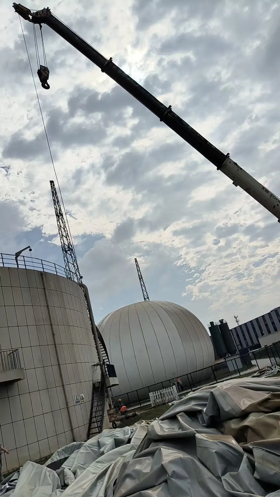
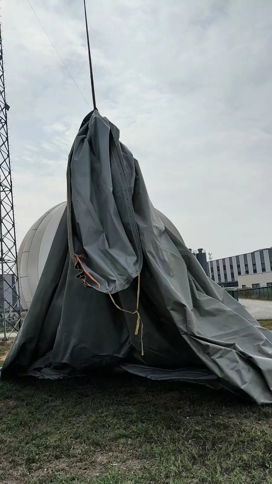
The white floor-standing gasholder in another photograph is adjacent equipment, not the tank-top gasholder being described here. Distinguishing it from the tank-top work area makes the relationship between the crane, membrane and crew easier to understand.
Recording the existing gasholder membrane condition
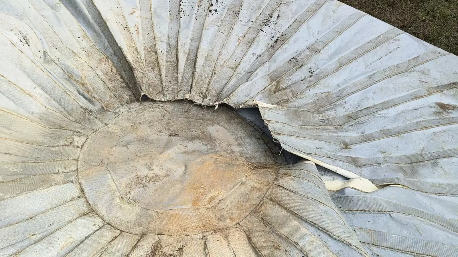
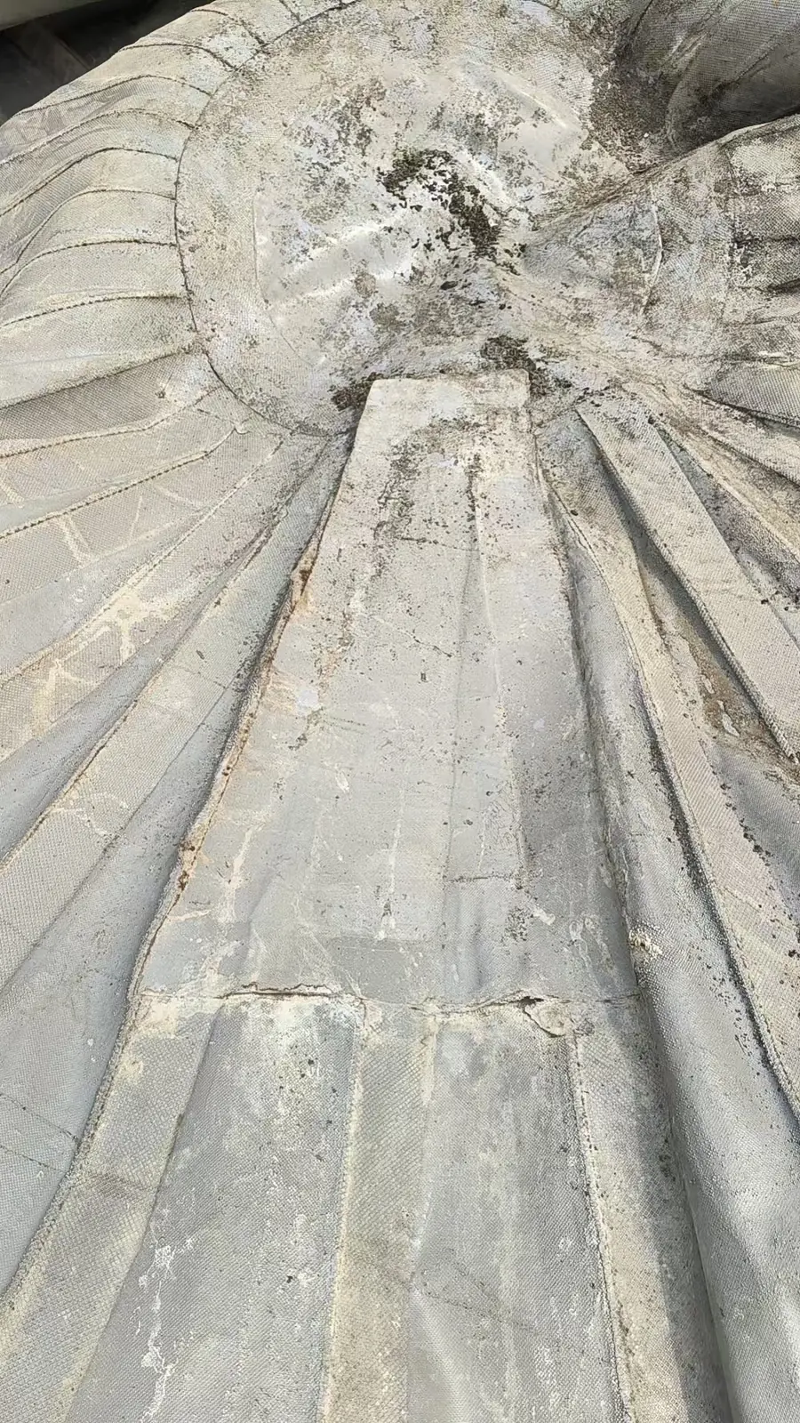
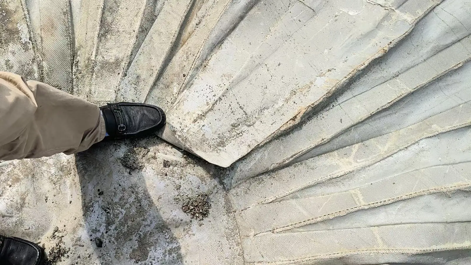
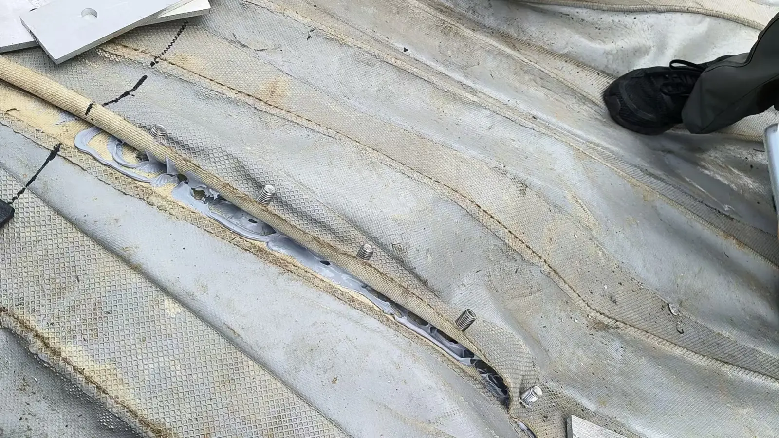
Close views around the crown show an opening, seams, surface deposits and local folds. They help locate the work area relative to the crown plate and radial seams; the images alone do not distinguish pre-existing damage from openings made during maintenance.
For this double membrane gasholder, the confirmed scope was local repair of the existing membrane followed by reinstallation. Retaining the existing membrane does not remove the need to assess its condition: appearance alone cannot establish the cause of damage, residual strength or remaining service life. Those assessments require supporting equipment records and evidence.
Preparing gasholder crown plates and connection materials
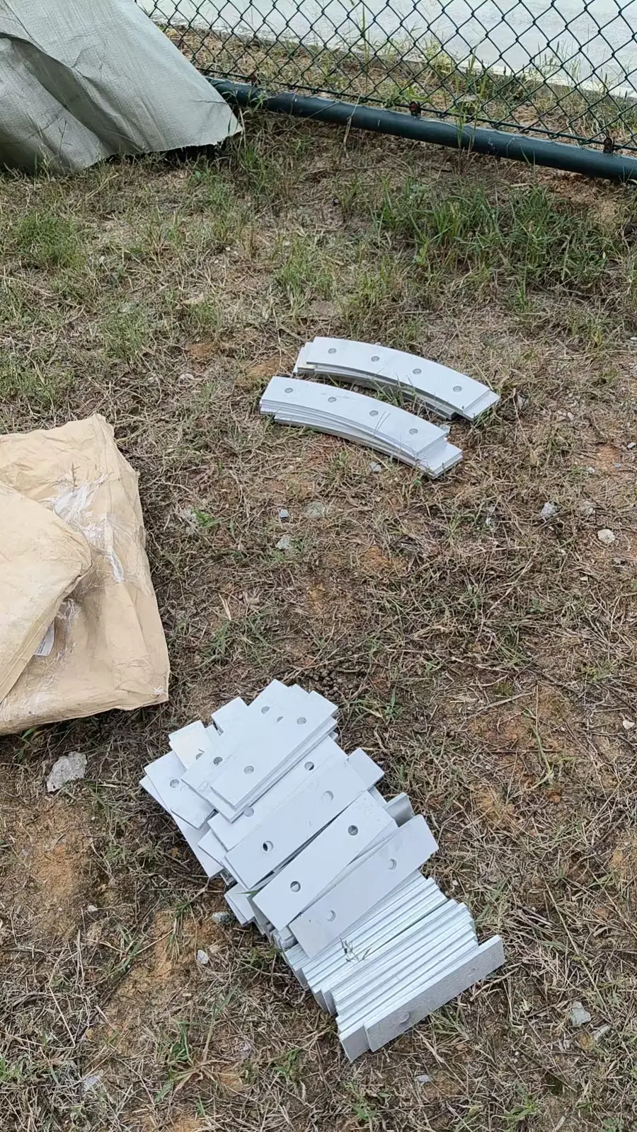
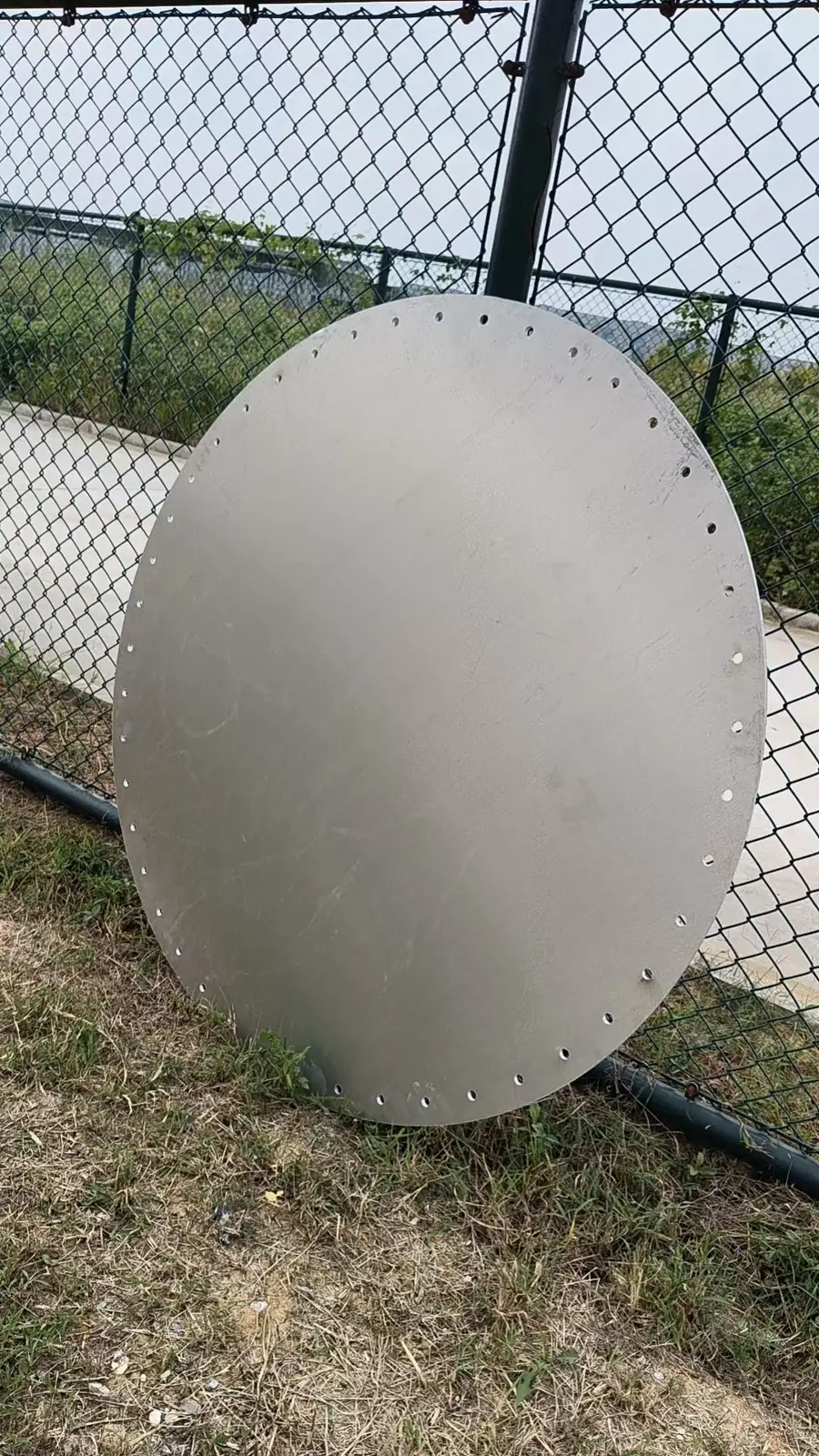
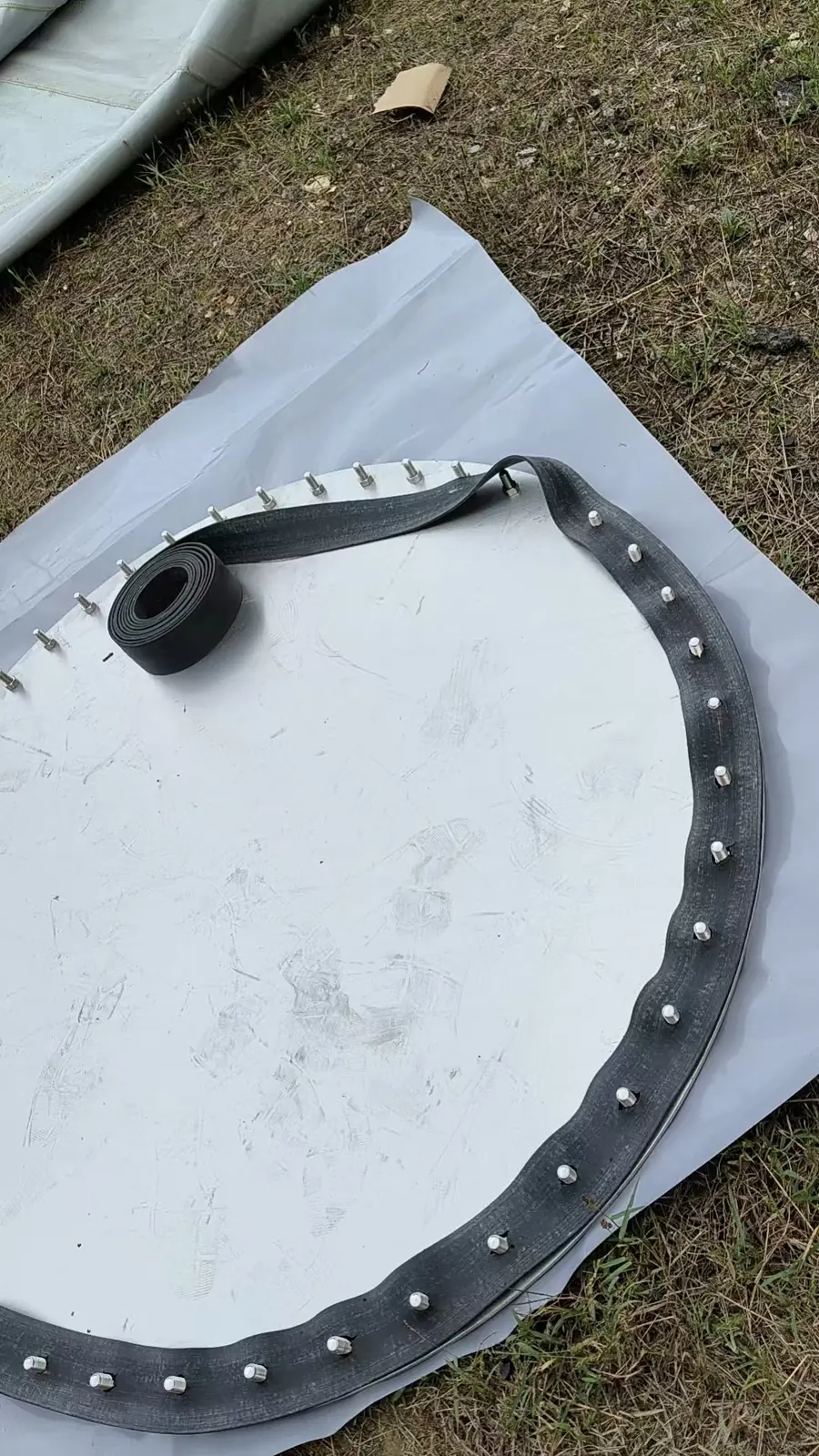
The site photographs show straight and curved clamping plates, a circular metal plate with perimeter holes, and a membrane piece marked for connection fit-up. The circular outlines and hole markings illustrate the need to match the membrane piece to its metal fittings.
Containers of maintenance supplies and reels of material are also visible. Preparation involves more than matching outlines: hole spacing, contact surfaces and compatible materials all need review so the membrane piece, crown plate, clamps and seals match the project repair specification.
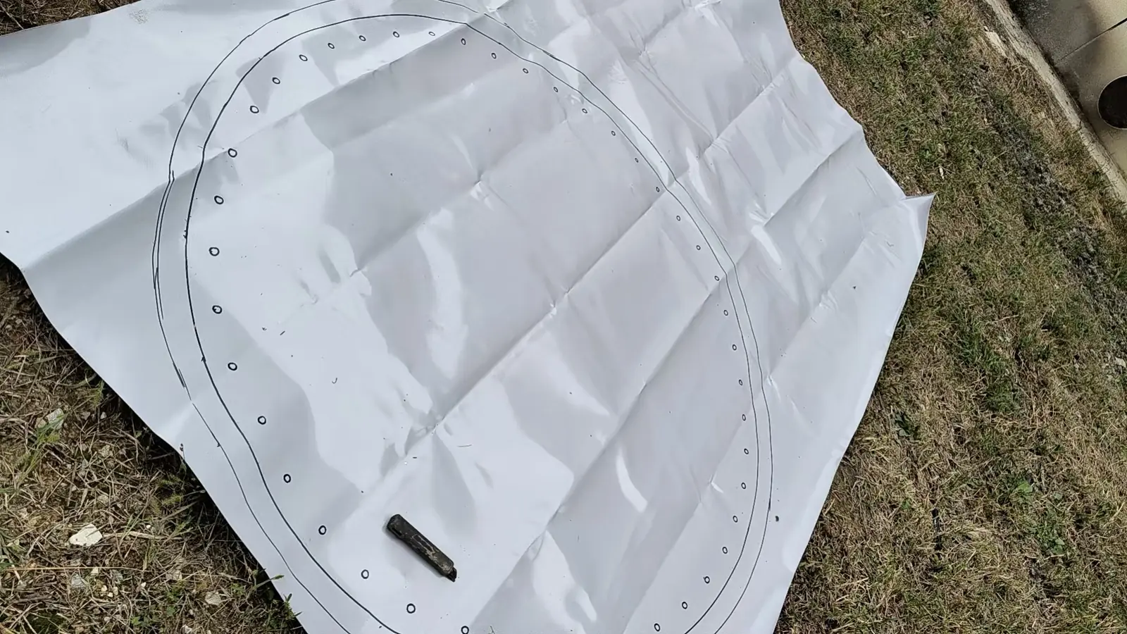
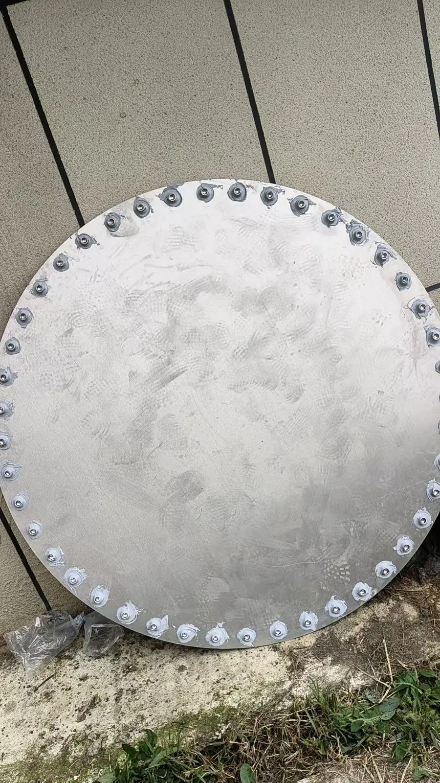
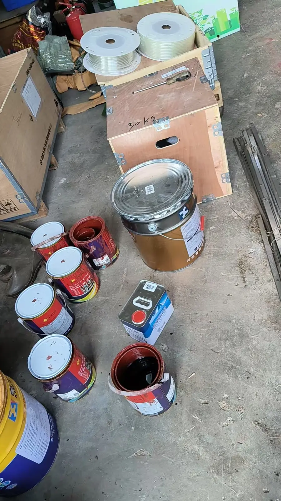
Crown-plate fit-up: membrane edge, seals and clamps
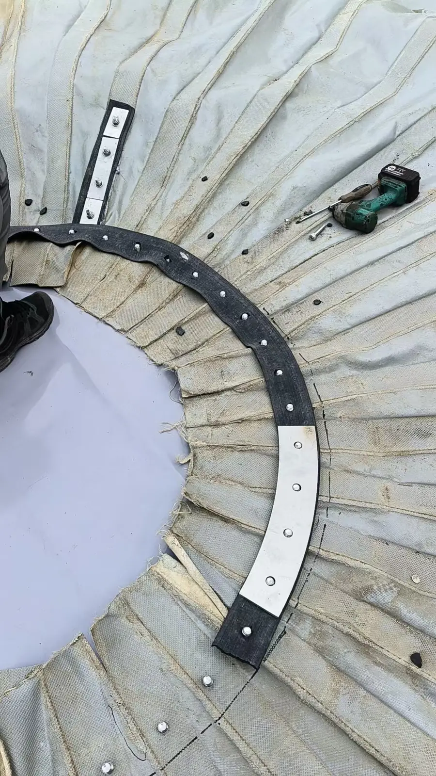
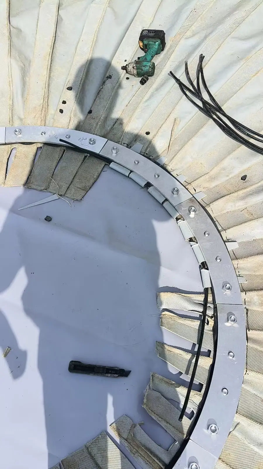
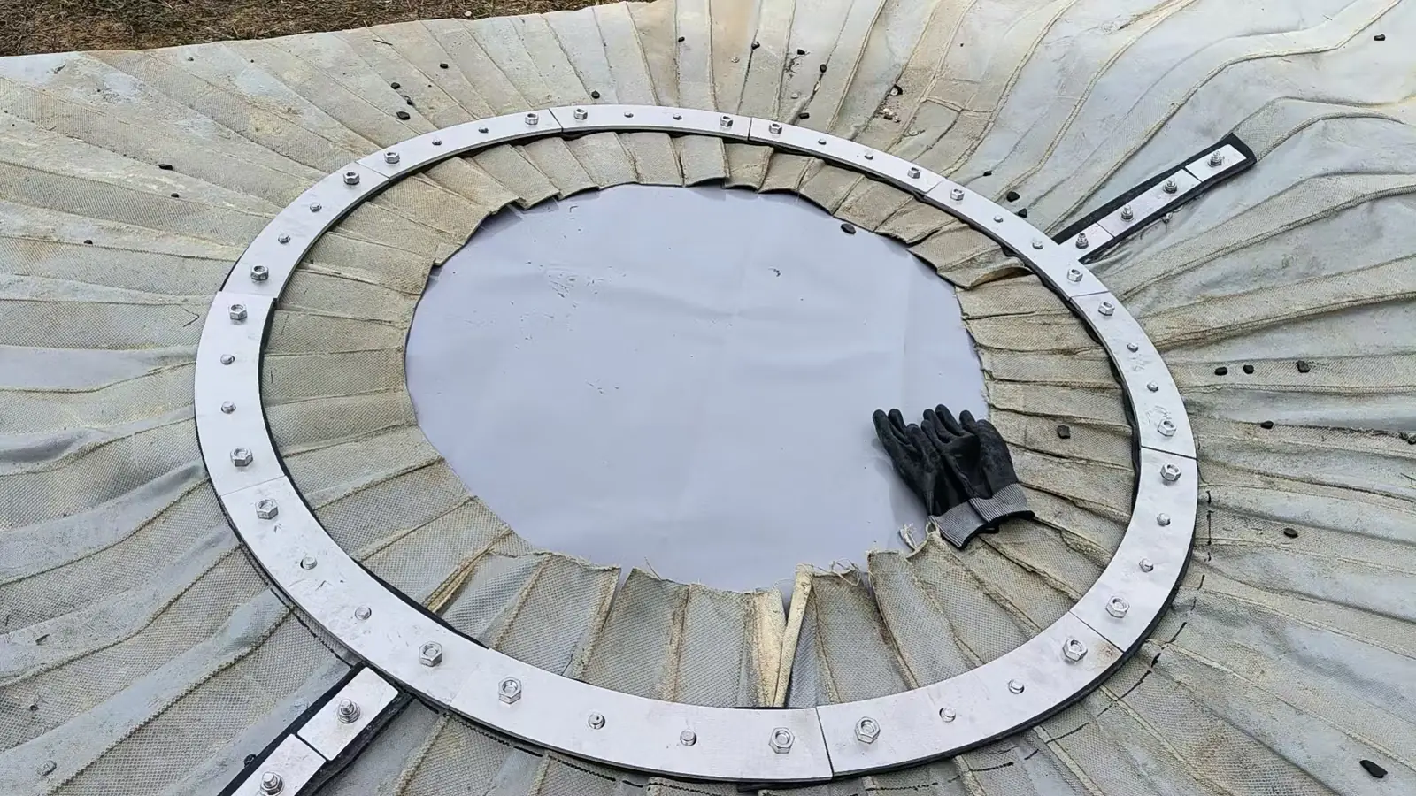
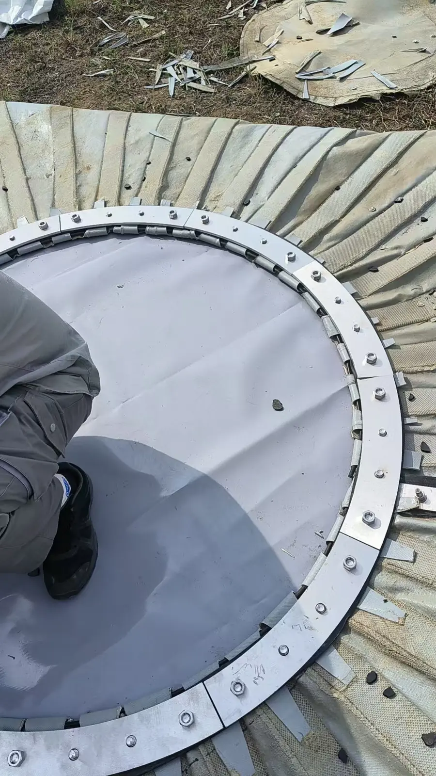
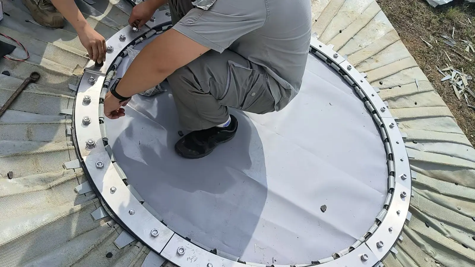
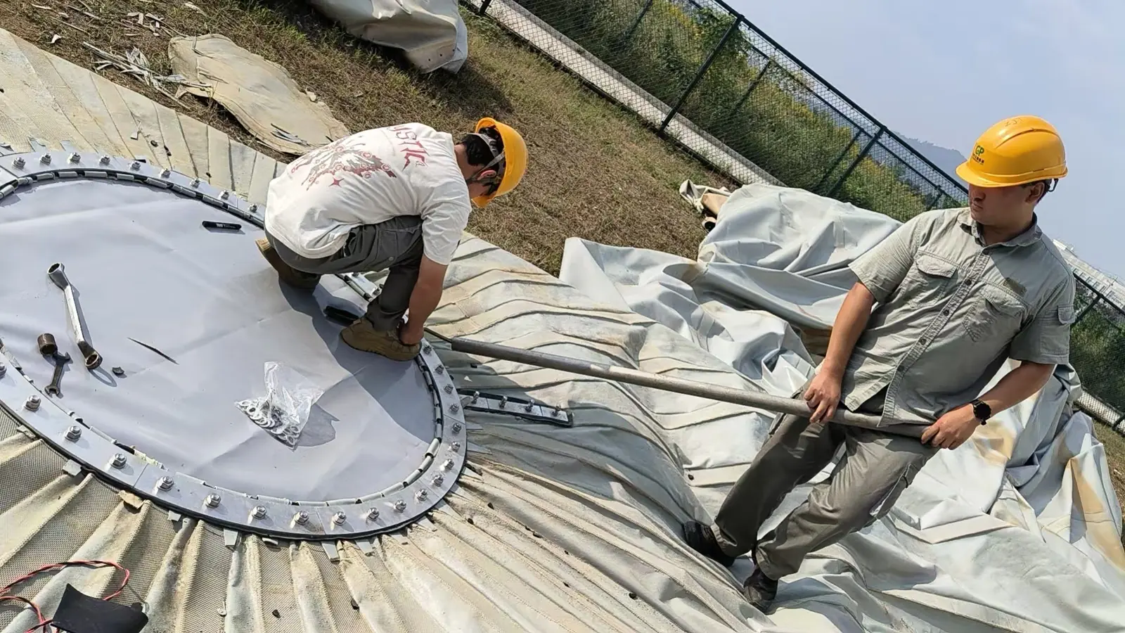
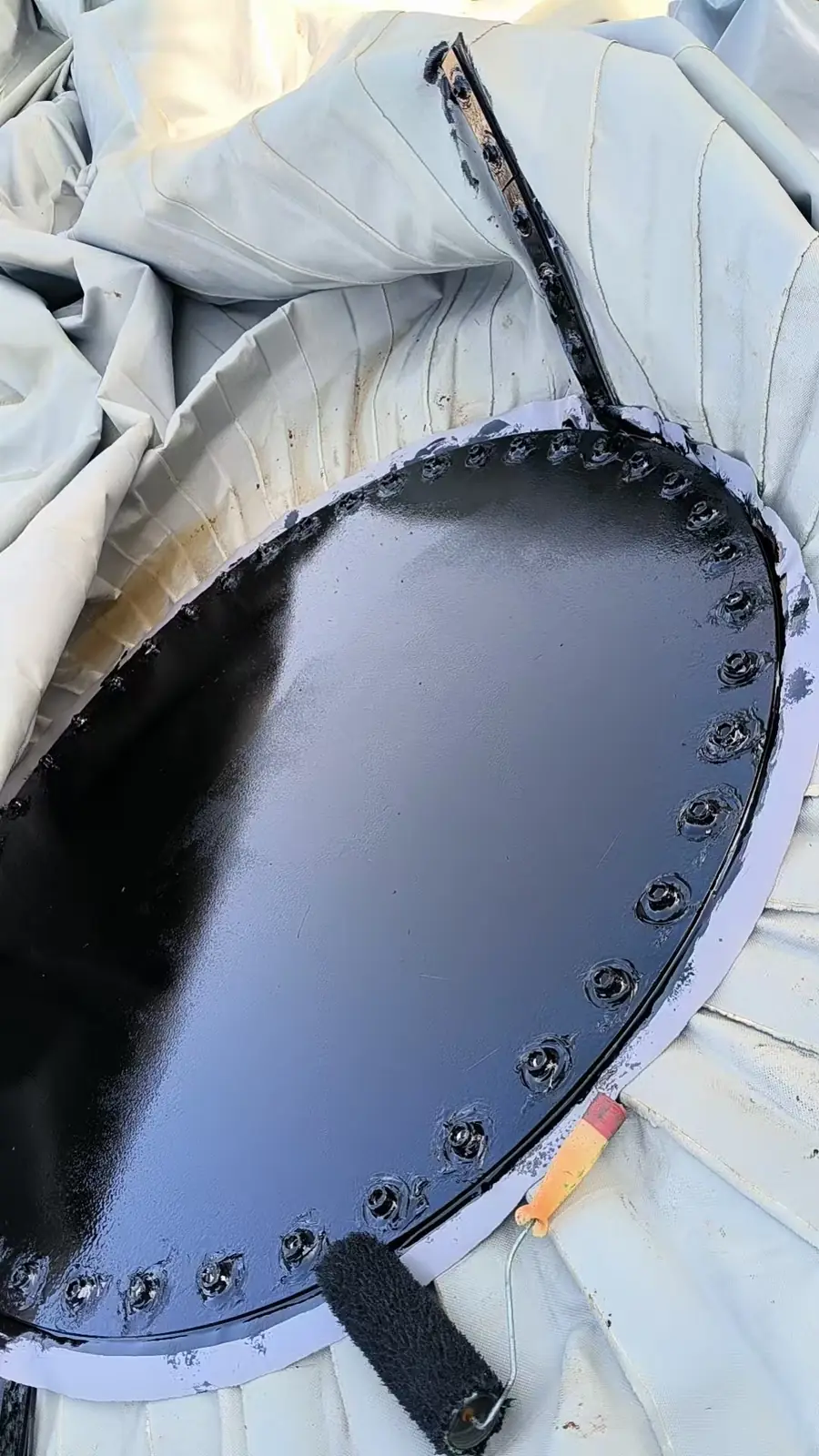
On this tank-top gasholder, several photographs show the circular crown connection in detail: membrane panels spread around the plate, black strip material at the contact interface, and segmented curved clamping plates with perimeter fasteners.
The views cover hole alignment, membrane-edge positioning, plate assembly and surface coating. The focus is the fit of the whole circular connection, not a single bolt: the membrane edge, sealing layer and segmented clamps must be addressed together under the approved connection design and repair procedure.
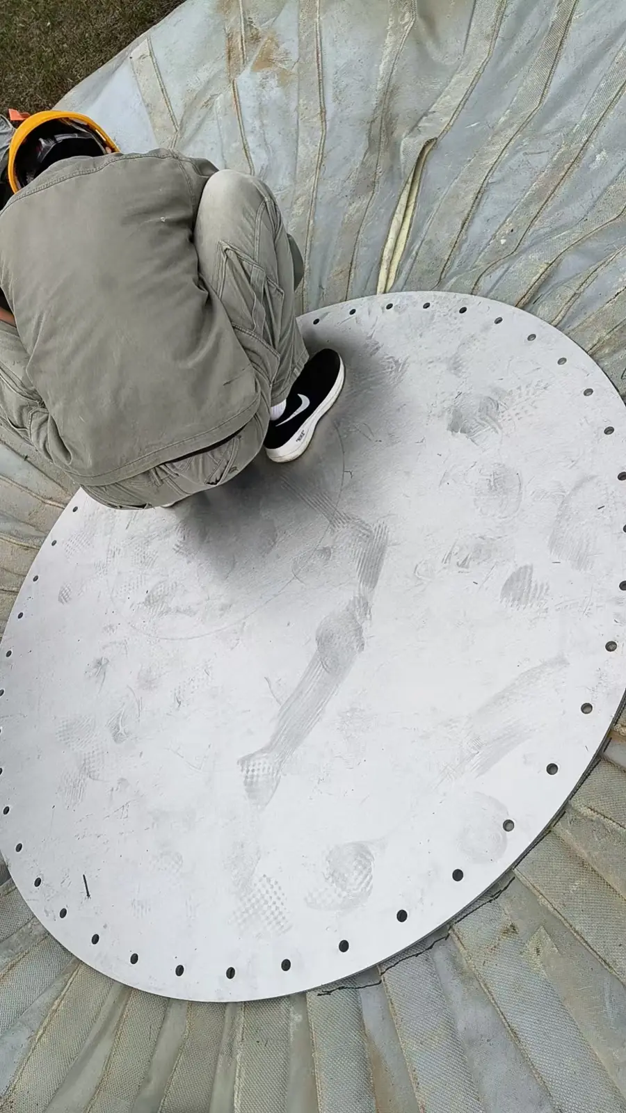
Local connections, straight clamps and valve fittings
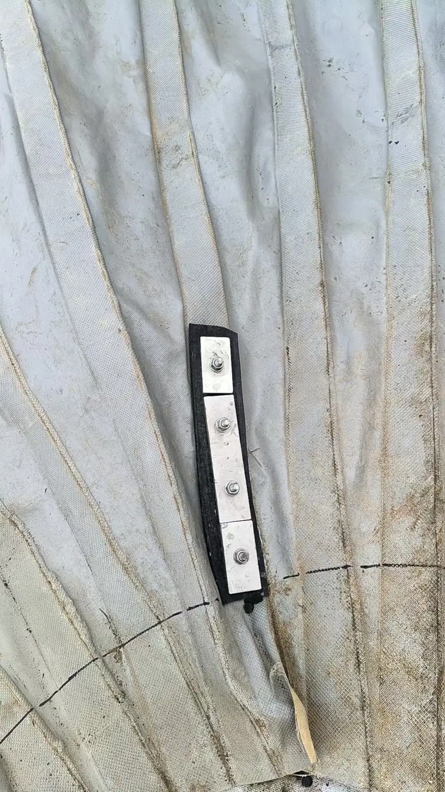
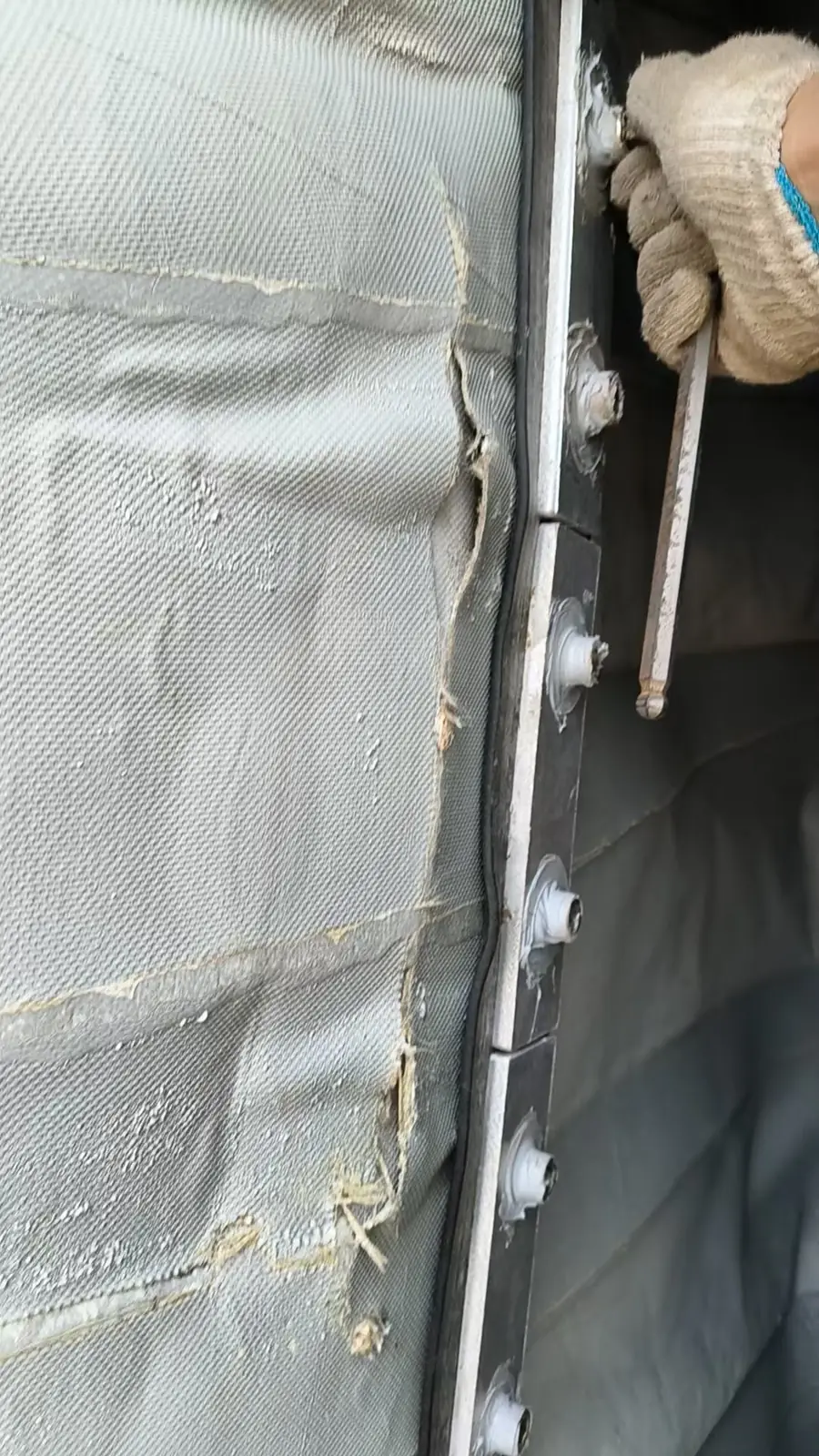
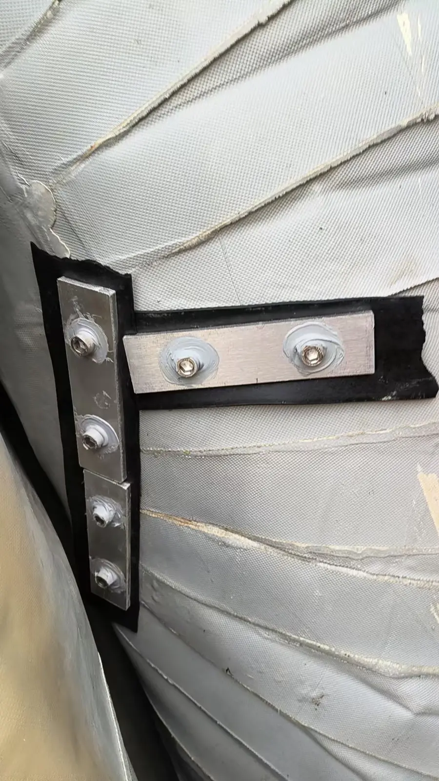
Beyond the circular crown connection, the photographs record local straight clamps, crossing strips, backing layers and fasteners. Local membrane repair on a double membrane gasholder must address these connections as well as the main fabric surface.
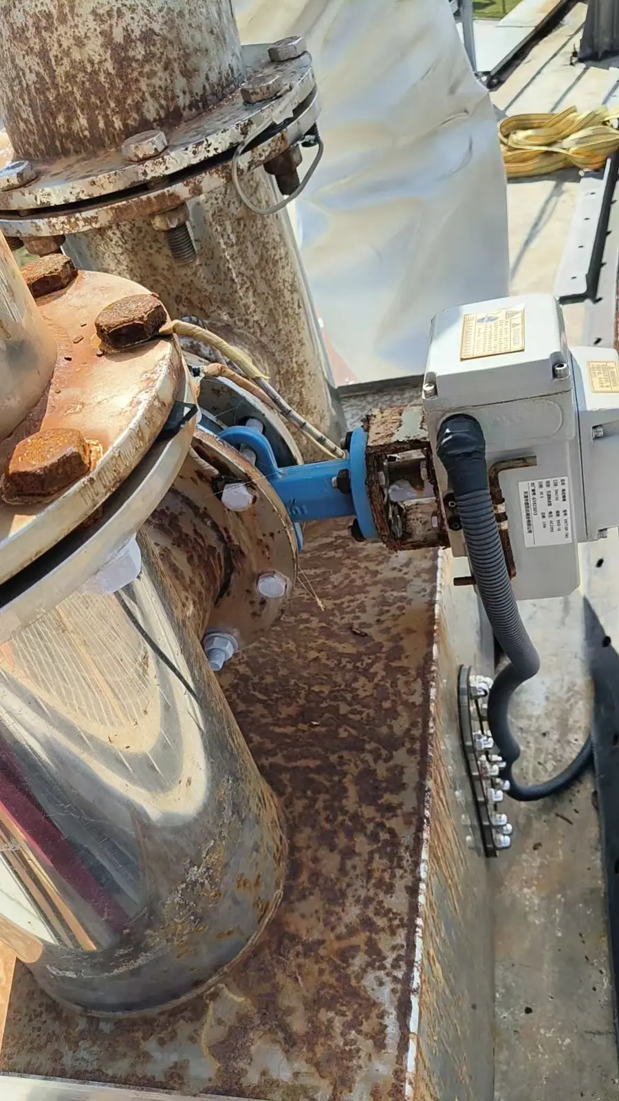
The pipework photograph shows a valve, electric actuator and flanges, with visible corrosion on some surrounding metal surfaces. We use the description “valve and actuator assembly” rather than identifying it as a non-return valve or drawing conclusions about its operation or tightness.
Lifting and reinstalling the tank-top gasholder membrane
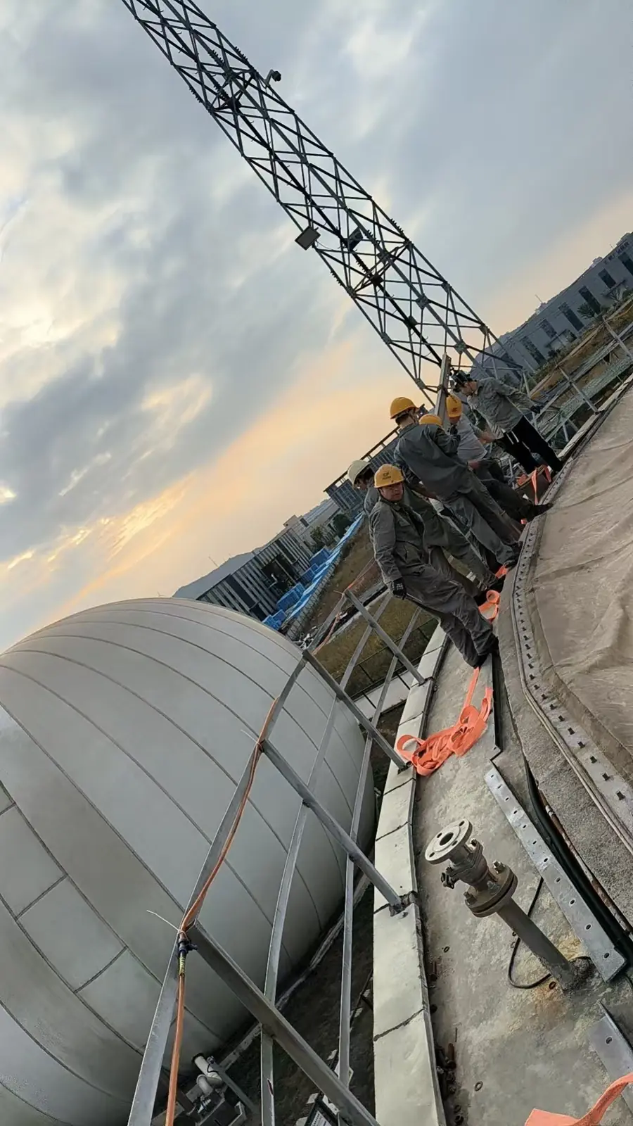
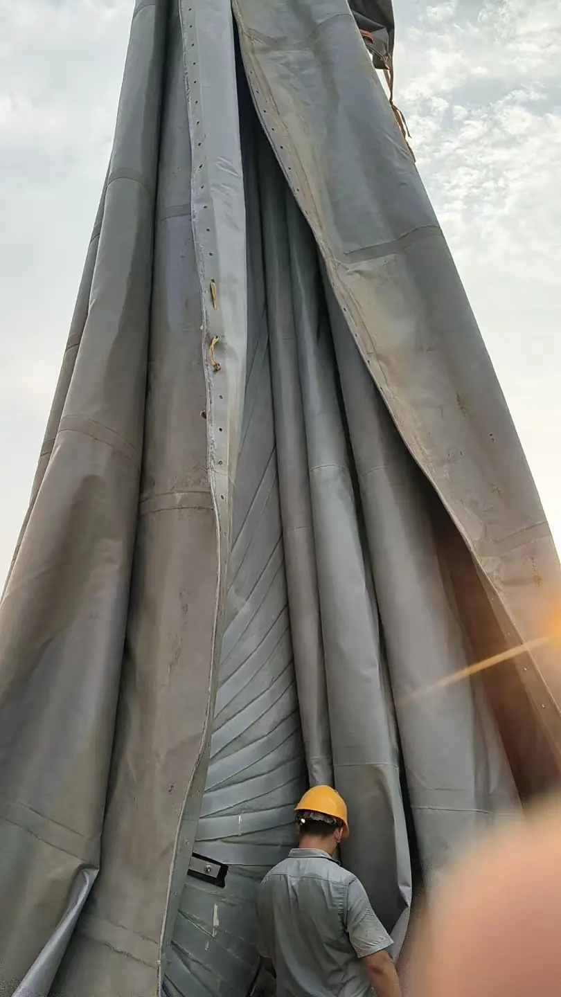
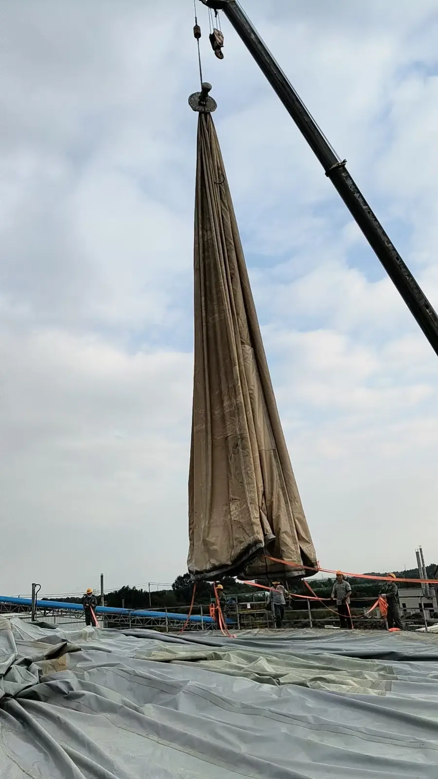
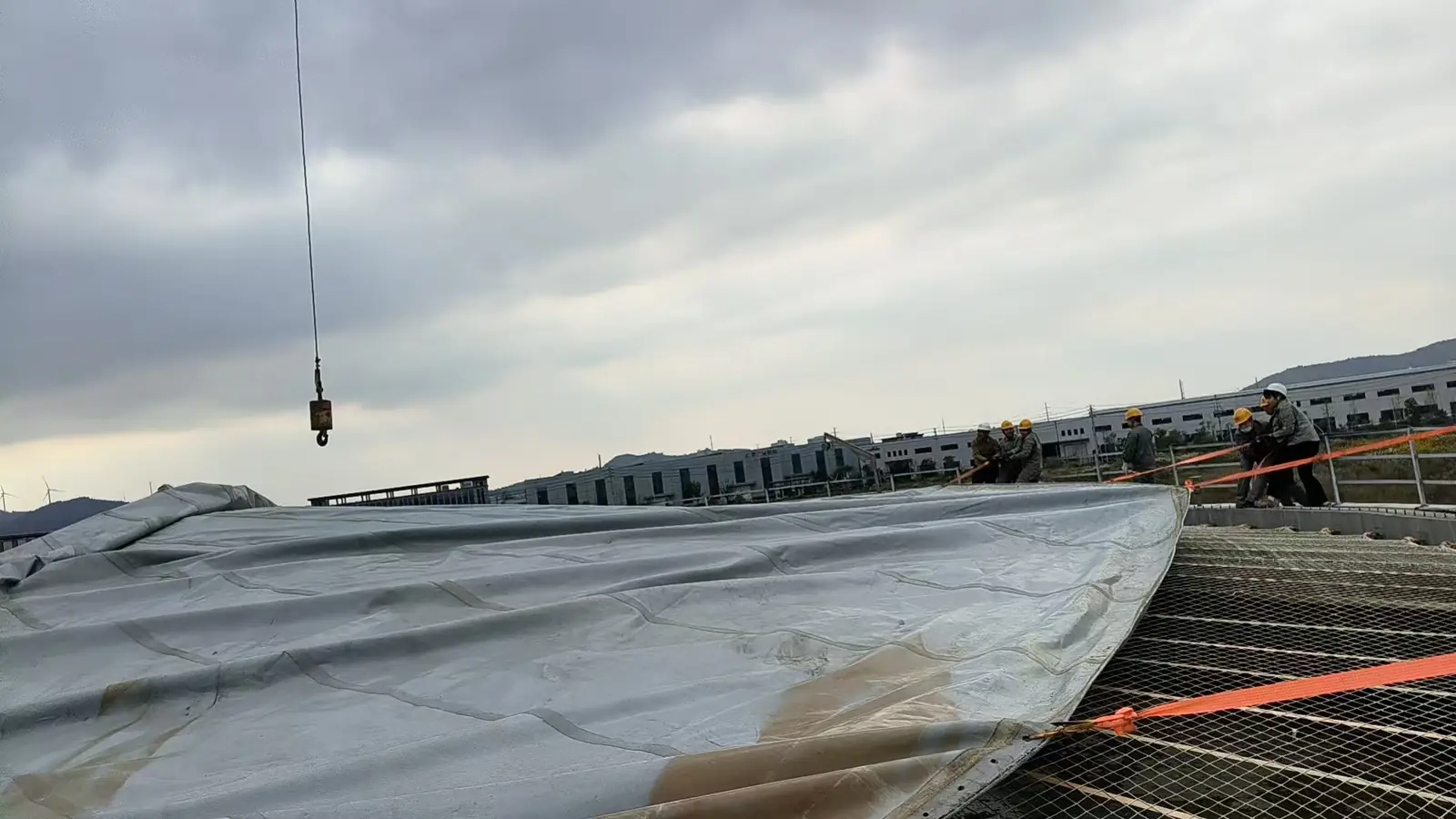
A crane raises the gathered membrane while the crew assists with guide lines and handling straps. Another view shows the membrane spread over the tank top, with support straps and netting visible beneath its right-hand edge.
The photographs show how the flexible membrane changes shape between a gathered upright bundle and a broadly spread sheet. This handling formed part of local repair and reinstallation of the existing membrane, not installation of a complete new inner-and-outer membrane set. Reinstallation also involves edge positioning, connection fit-up and fastening; it is not represented by a single lift.
Before the gasholder returns to service: checks and handover
Readiness to restart the gasholder must be established through the project procedure: checking the membrane and connections, leak tightness and relevant equipment functions, and recording the handover. This photo set does not include those results or restart approval, so the record ends with the field activities. To discuss your own double membrane gasholder, provide MOTET with its installation type, equipment documentation, damage photographs and previous maintenance records so the repair scope can be defined first.
Frequently asked questions
Were the complete membranes of this double membrane gasholder replaced?
No. This Anhui gasholder project involved local repair of the existing membrane followed by reinstallation, not replacement of the complete inner and outer membranes. The article records the existing membrane, crown and clamping connections, lifting and reinstallation; it does not describe a new-membrane supply or full replacement project.
What information helps assess local repair of a gasholder membrane?
Provide the installation type, original design and membrane documentation, dimensions and interface drawings, close and wide photographs of the damage, and previous maintenance records. Photographs help locate an issue, but equipment documents and a site assessment are needed to confirm the repair scope.
Do these photographs show that the gasholder passed acceptance and returned to service?
No. They document maintenance-related activities and component details, not leak-test results, functional checks, acceptance records or approval to restart. This article does not claim that the holder has returned to service.