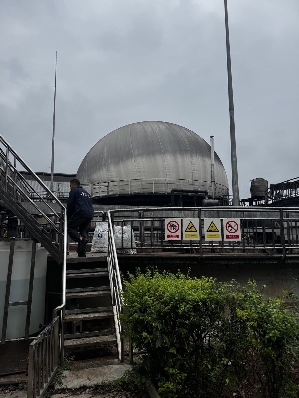
Inner-membrane replacement is not a fabric swap. It starts by establishing why the original system failed and whether the retained outer membrane, interfaces, clamping, sealing, instrumentation and support-air equipment are fit for the rebuilt system.
1. Define the Retrofit Boundary: Retain the Outer, Replace the Inner
The first inspection covers the outer-membrane surface and seams, penetrations, support-air system and perimeter clamping. The fact that an outer membrane can still inflate does not by itself make it reusable; cracking, embrittlement, severe wear and permanent distortion must be assessed.
The project therefore retained the outer membrane but rejected the failed inner membrane and several legacy interface details. Part 1 covers inspection, controlled deflation, protective lifting of the outer membrane, removal of the old inner membrane and exposure of the base interfaces.
Safety boundary
This article illustrates workflow and field observations. It does not replace a project method statement, work permit, gas-testing plan, energy-isolation procedure, lift plan or local law. Biogas may present flammable, toxic and asphyxiating hazards; competent authorised personnel must perform the work.
2. Inspect Before Dismantling: Failures Often Start at Interfaces
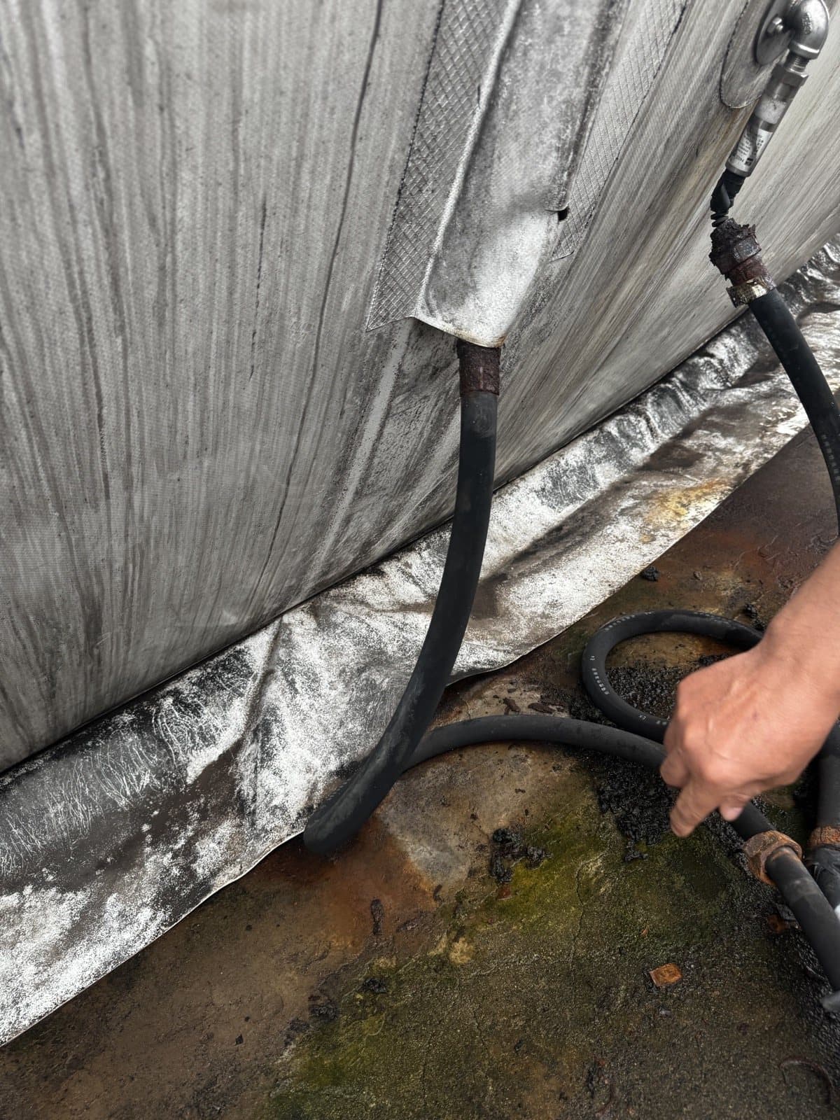
The photographs show temporary wraps and localised sealing around cable and hose penetrations, without a clear load path, strain relief or inspectable continuous seal. A membrane boot is an engineered penetration—not a cosmetic bag placed over an interface.
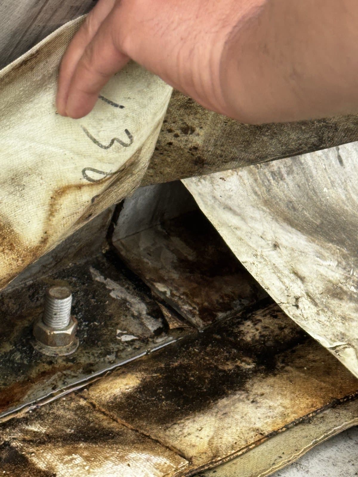
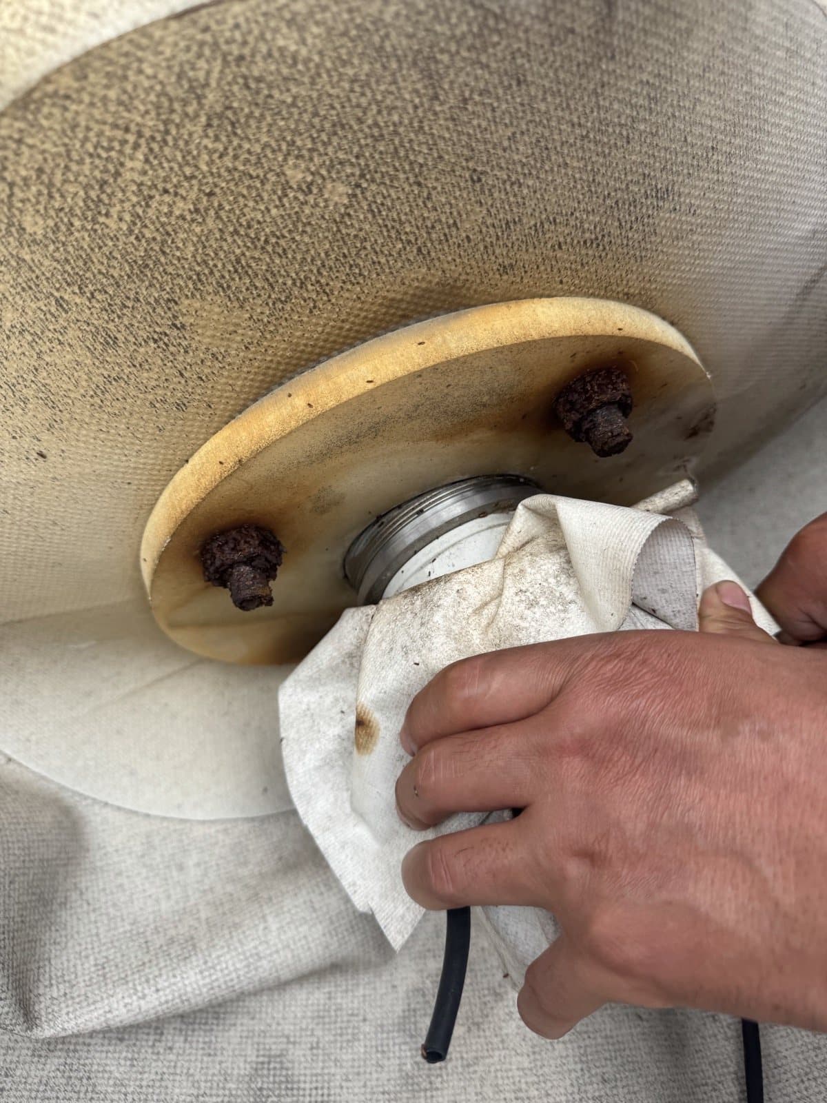
The level instrument, flange and signal cable must be inspected as one assembly. A working signal does not prove that the flange seal, bolts, corrosion protection and cable restraint are acceptable.
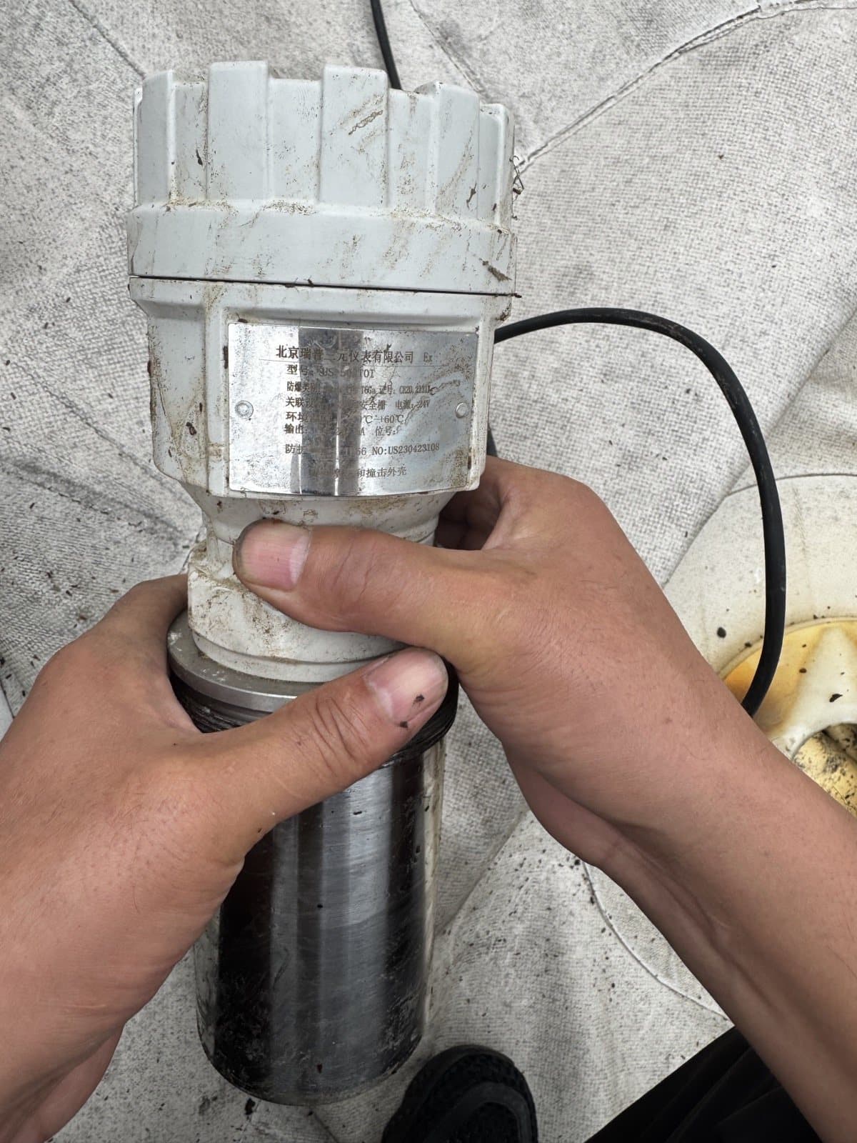
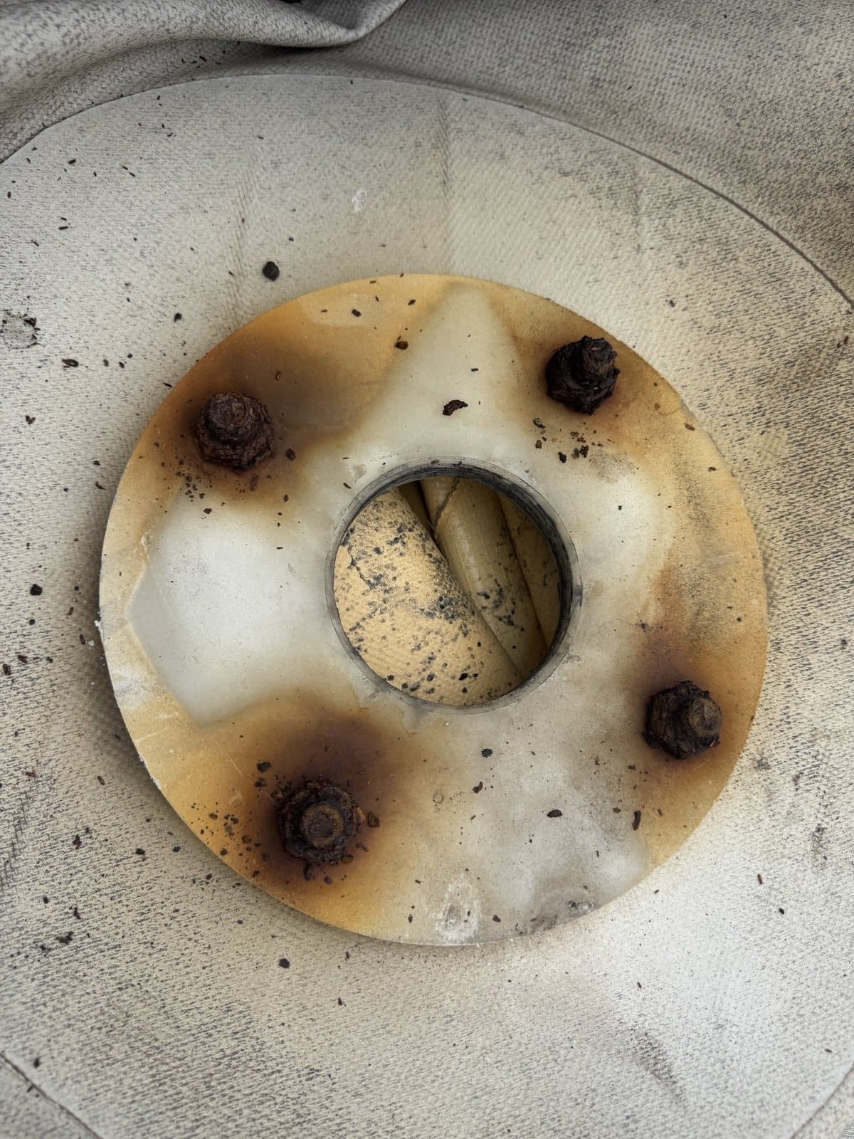
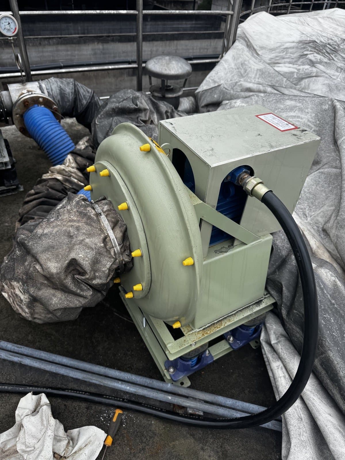
01
Seal not inspectable
Multiple wraps and local sealant conceal the actual contact surfaces.
02
Unclear load path
Hose and cable loads may be transferred directly into the membrane.
03
Poor maintainability
Bolts, flanges, seams and gaskets cannot be verified before dismantling.
3. Controlled Deflation: More Than Letting the Dome Collapse
Before dismantling, gas inlet and outlet, connected process, residual pressure and hazardous energy must be isolated under the approved plan, with continuing atmosphere verification. The outer membrane is then lowered progressively to avoid abrupt folds and loads on fittings.
General guidance does not replace a site-specific method statement. EPA AgSTAR treats inspection, maintenance and safety as dedicated topics, while OSHA 1910.147 emphasises controlling, isolating and verifying hazardous energy before maintenance. Local law and owner procedures govern the actual project. EPA AgSTAR · OSHA 1910.147
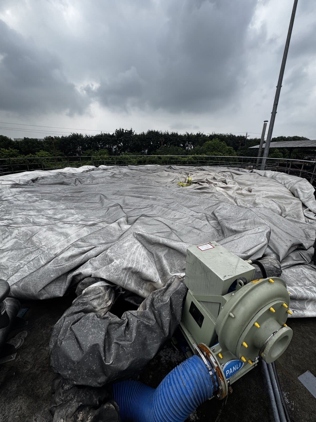
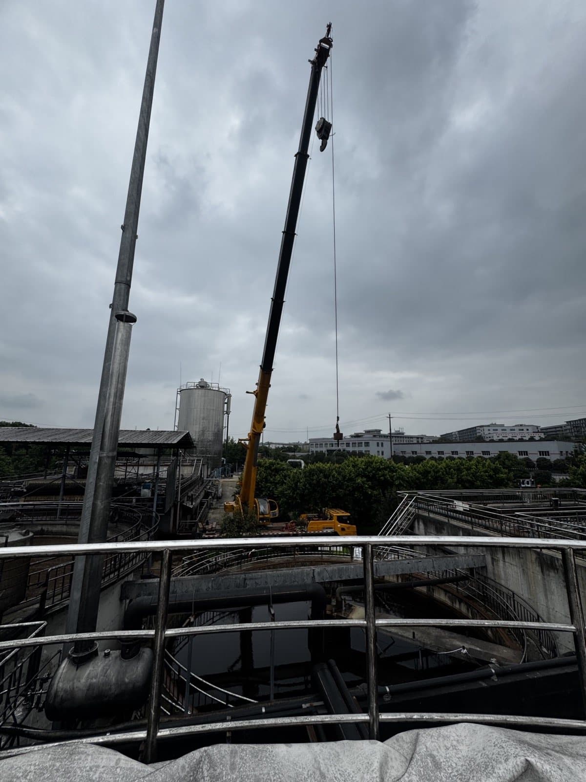
4. Retaining the Outer Membrane: Lift Without Damage
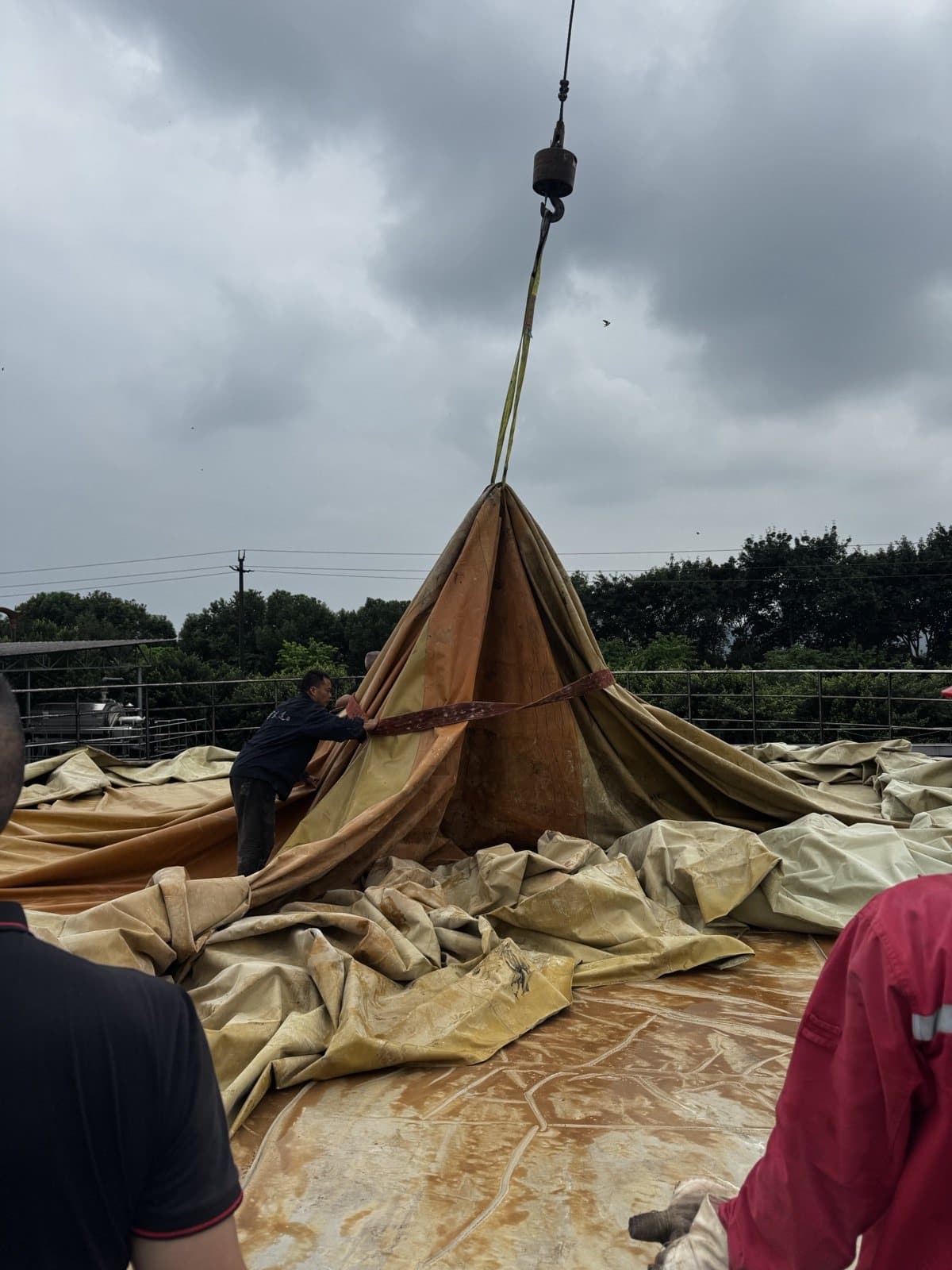
Because the outer membrane will be reused, the lift is not a demolition exercise. Orientation references are retained, the membrane is gathered at verified support positions and ground personnel prevent dragging across bolts, railings, sharp clamping edges or contaminated surfaces.
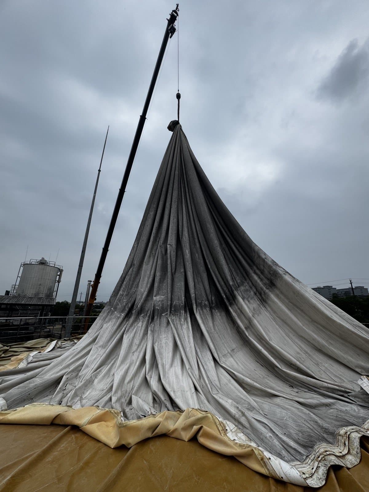
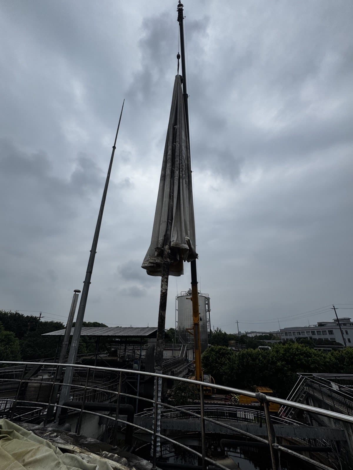
5. Once the Outer Membrane Is Lifted, the Failure Becomes Visible
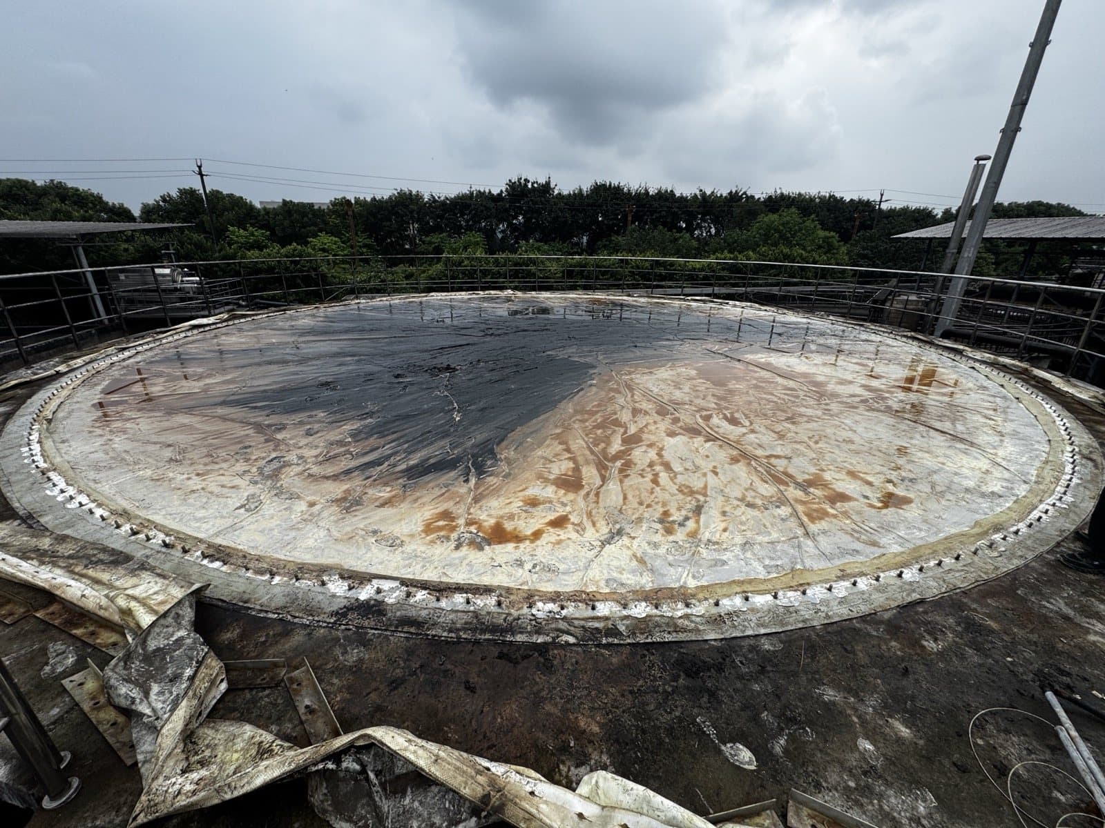
The old inner membrane carried widespread yellow-brown contamination, retained liquid and deposits. Although some are commonly called sulfur paste on site, a professional record separates observation from chemistry: photographs confirm deposits, not composition. Sampling is appropriate if the result affects material selection, cleaning or disposal.
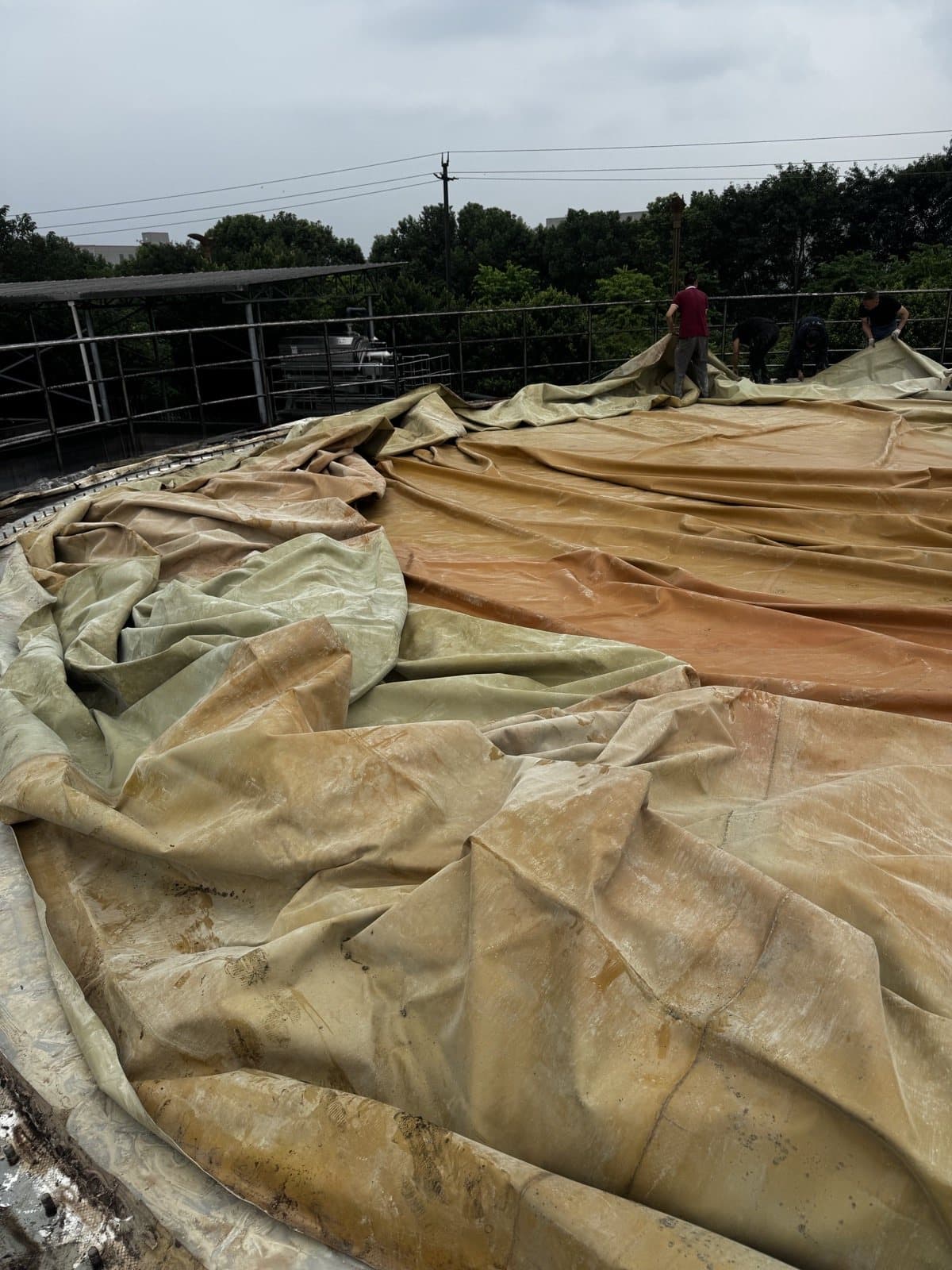
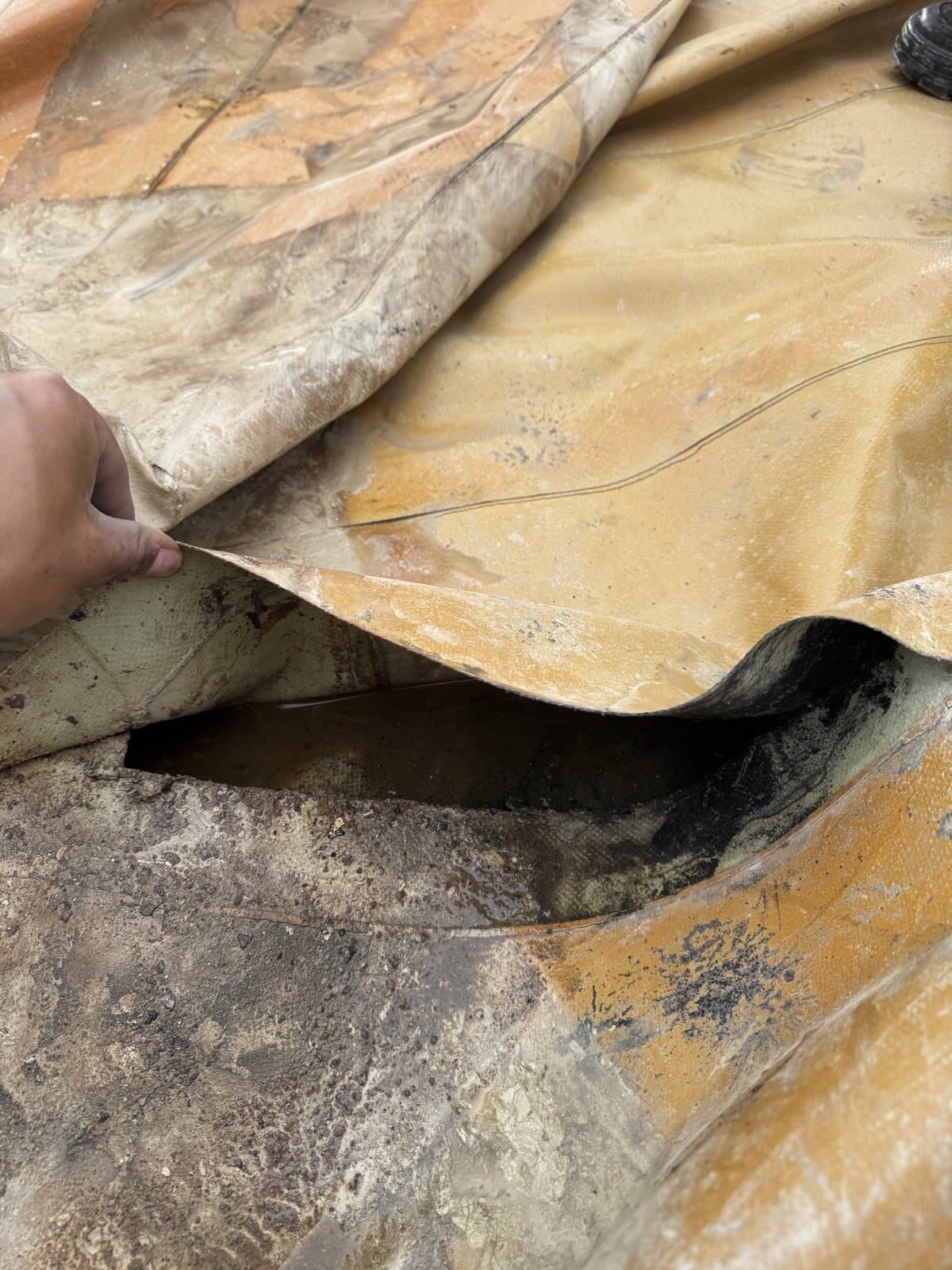
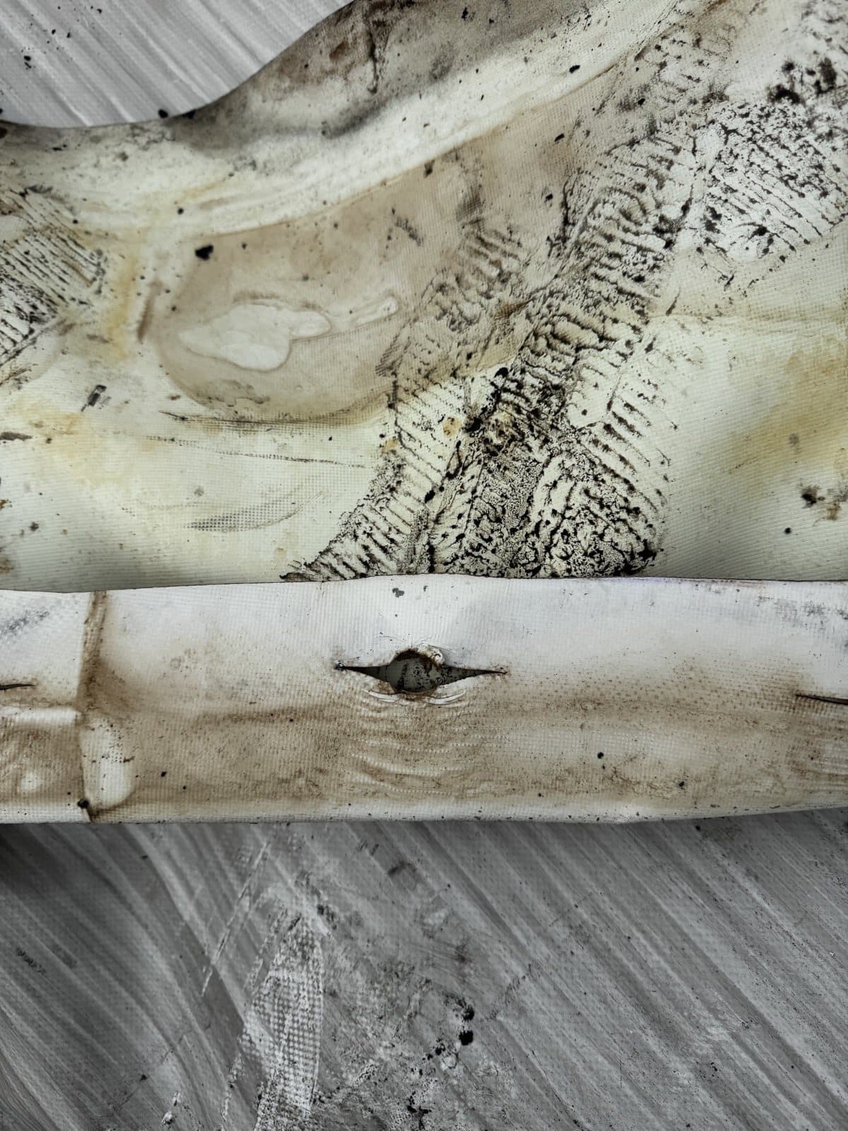
Engineering interpretation
This is not a defect that can be understood by adding a patch. It exposes system risk across membrane material, welding parameters, seam layout, cyclic loading, chemical environment and perimeter restraint. Without samples and operating records, the defensible conclusion is “joint failure confirmed; root cause requires verification.”
6. Remove the Old Inner Membrane and Expose the True Base Condition
The old membrane is released progressively from the perimeter, gathered and lifted away. Corrosion and contamination on channels, pressure bars and fastener locations mean that a new membrane cannot simply be laid over the old interface. Reuse must be decided from section loss, flatness, hole condition, sharp edges and corrosion protection.
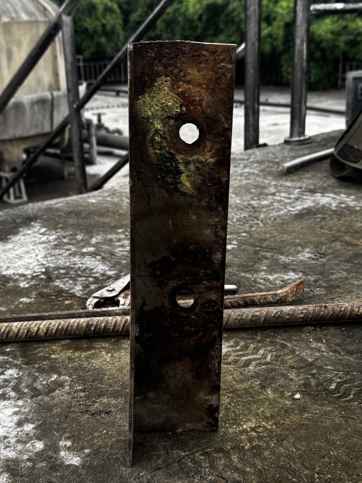
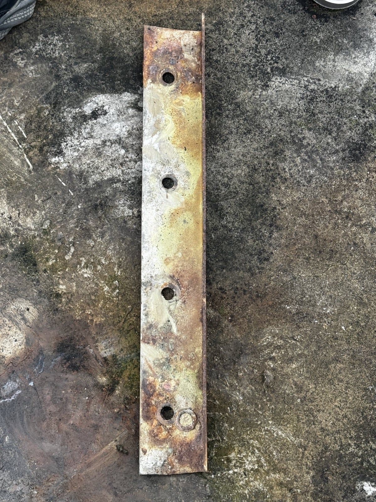
7. Seven Details That Separate Professional Work from a Temporary Fix
Use continuous, flat, edge-safe pressure bars with verified hole and load distribution.
Use a continuous compatible sealing strip; do not replace controlled compression with arbitrary caulking.
Engineer membrane boots and penetrations so they can be welded, inspected and maintained.
Provide independent cable and hose restraint so weight, vibration and pull are not carried by the membrane.
Control the welding window and retain samples or records; a smooth appearance alone does not qualify a joint.
Commission blowers, regulation, pressure and level signals, alarms and interlocks as one system.
Before the new membrane arrives at the interface, clean, dry and formally release the base, flange, clamps and work area.
8. What Part 2 Will Cover
Part 2 moves from a clean, released interface to a new membrane installed for reliable service.
- Base, flange and clamp preparation
- New membrane orientation and positioning
- Continuous gasket and progressive clamping
- Penetration, level and cable reinstatement
- Retained outer-membrane reinstatement
- Controlled inflation, leak and functional checks
Frequently Asked Questions
Can the inner membrane be replaced while retaining the existing outer membrane?
Yes, when the outer membrane, seams, fittings and remaining serviceability pass inspection. It must be protected, orientation-marked and handled as a retained component throughout the work.
Why is the existing outer membrane lifted during an inner-membrane replacement?
Controlled lifting can create access for inspection and removal of the inner membrane without discarding the serviceable outer membrane. The approved lift plan must define support points, weather limits and handling controls.
What is the yellow-brown material found on the old inner membrane?
It may be condensate-borne, sulfur-containing or process-derived deposit, often called sulfur paste on site. Its exact composition cannot be confirmed from appearance alone and requires sampling if the result will affect material selection or cleaning.
Does a torn seam prove that welding was the only cause?
No. A tear along a seam is evidence that the joint system has failed, but the cause may include inadequate fusion, geometry, cyclic stress, ageing or chemical exposure. A defensible conclusion requires inspection of the fracture surface and operating history.
Can sealant replace the perimeter sealing strip?
Not as a default design choice. A continuous, compatible sealing strip provides a controlled compression interface. Site-applied sealant may be supplementary only when the approved design specifically requires it.
What will Part 2 cover?
Part 2 will cover base preparation, new inner-membrane positioning, perimeter sealing and clamping, penetrations, outer-membrane reinstatement, controlled inflation, leak checks and functional commissioning.
Inner-membrane retrofit inquiry
Understand the failed interfaces before specifying the replacement.
Share the gas-holder arrangement, dimensions, gas service, failure photographs and shutdown window. MOTET can assess outer-membrane retention, inner-membrane scope and site constraints.