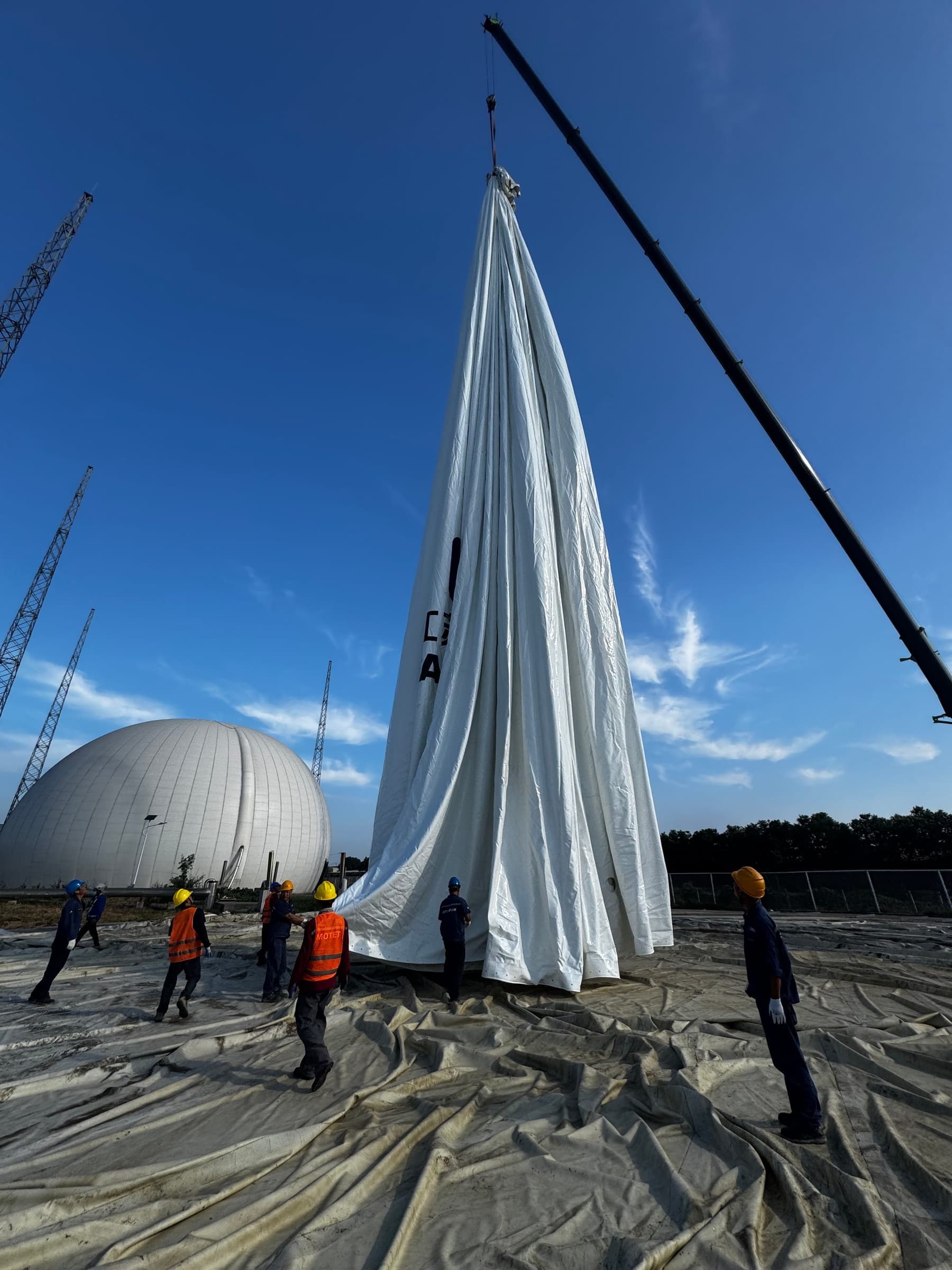
Outer-membrane replacement is not simply an exchange of fabric. It is a controlled rebuild of the interfaces between the membrane, perimeter anchorage, sealing system, protective coating, support-air equipment and controls. A weak interface can compromise an otherwise new membrane.
1. Decide First: Patch or Full Replacement?
The outer membrane forms the weather enclosure and helps maintain the gas holder profile. An isolated defect may be repairable when the surrounding material remains sound and the membrane supplier approves the repair method. A patch, however, cannot restore weather resistance or dimensional stability to a membrane that is ageing as a whole.
A local repair may be evaluated
- The defect is isolated and fully inspectable
- Adjacent coating, reinforcement and seams remain sound
- Repair materials are compatible with the original membrane
- The supplier procedure permits an on-site repair
Full replacement should be evaluated
- Widespread chalking, cracking or coating loss
- Repeated failures at seams, fittings or fold lines
- Distortion prevents balanced re-tensioning
- Repeated outages and repair risk are no longer acceptable
2. Before Work: Establish the Safety Boundary
Before membrane work starts, the responsible project team must implement an approved shutdown and work plan. The gas holder and connected process must be placed in a safe condition, with gas, support-air, electrical, valve and other hazardous-energy sources isolated. Gas testing, ventilation, lifting, weather, electrostatic control and hot-work or non-sparking-tool requirements must also be defined.
Safety boundary
This article illustrates the workflow; it does not replace a site method statement, work permit, gas-testing plan, lift plan or local regulatory requirements. Biogas is flammable and may contain toxic or asphyxiating constituents. The work must be performed by competent, authorised personnel.
3–5. Remove the Old Membrane and Restore the Clamping Steelwork
Open the clamping system in controlled sections
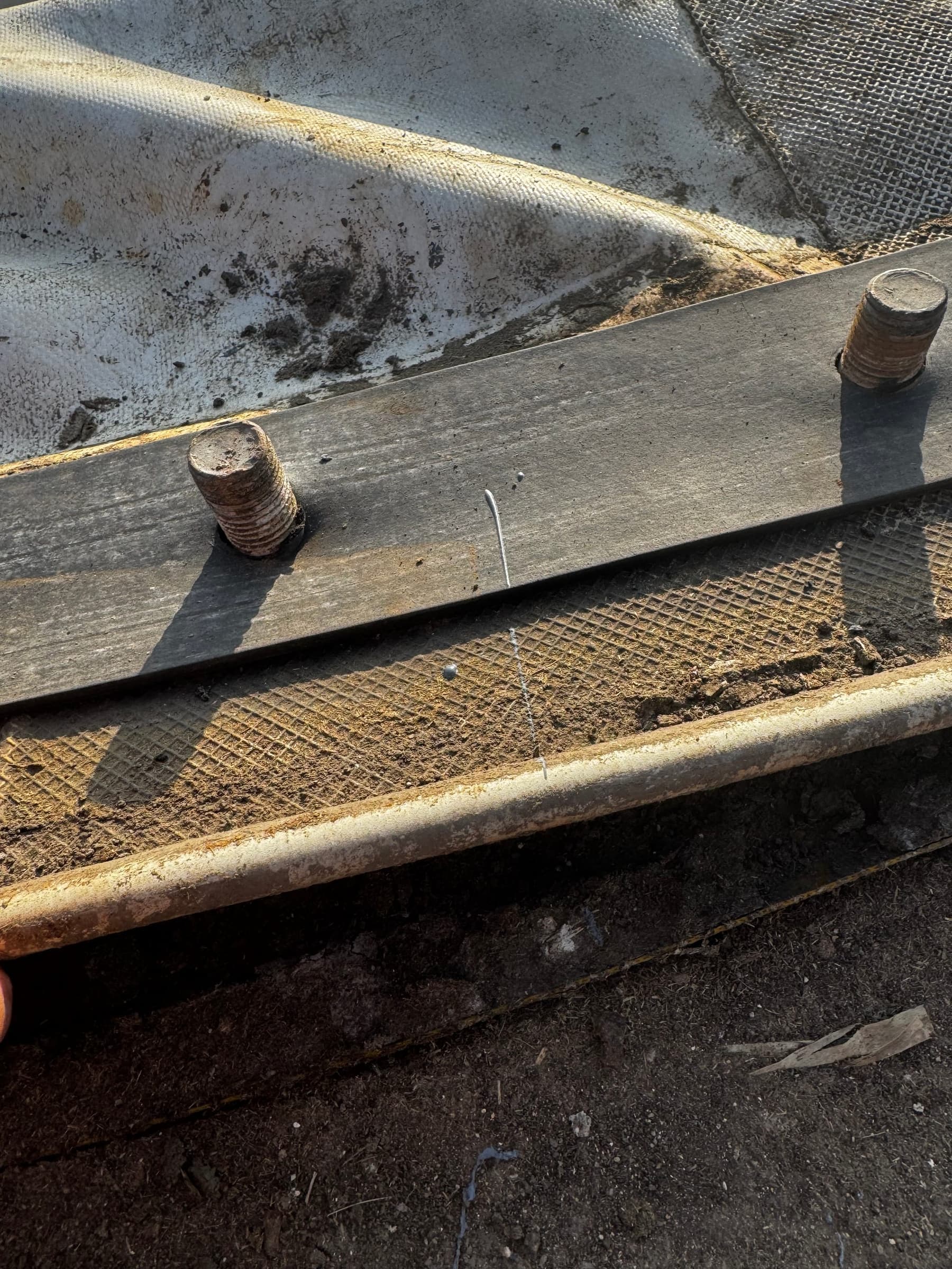
The perimeter assembly should be released in planned sections so that residual membrane force cannot cause uncontrolled movement. Once the old edge is removed, trapped moisture, debris, corrosion, distortion, loose fasteners and sharp burrs become visible.
QA hold pointRecord the original order, direction and abnormal locations of clamping bars, angle steel, anchors, washers, sealing strip and membrane edge.
Remove rust, failed coating and sharp edges
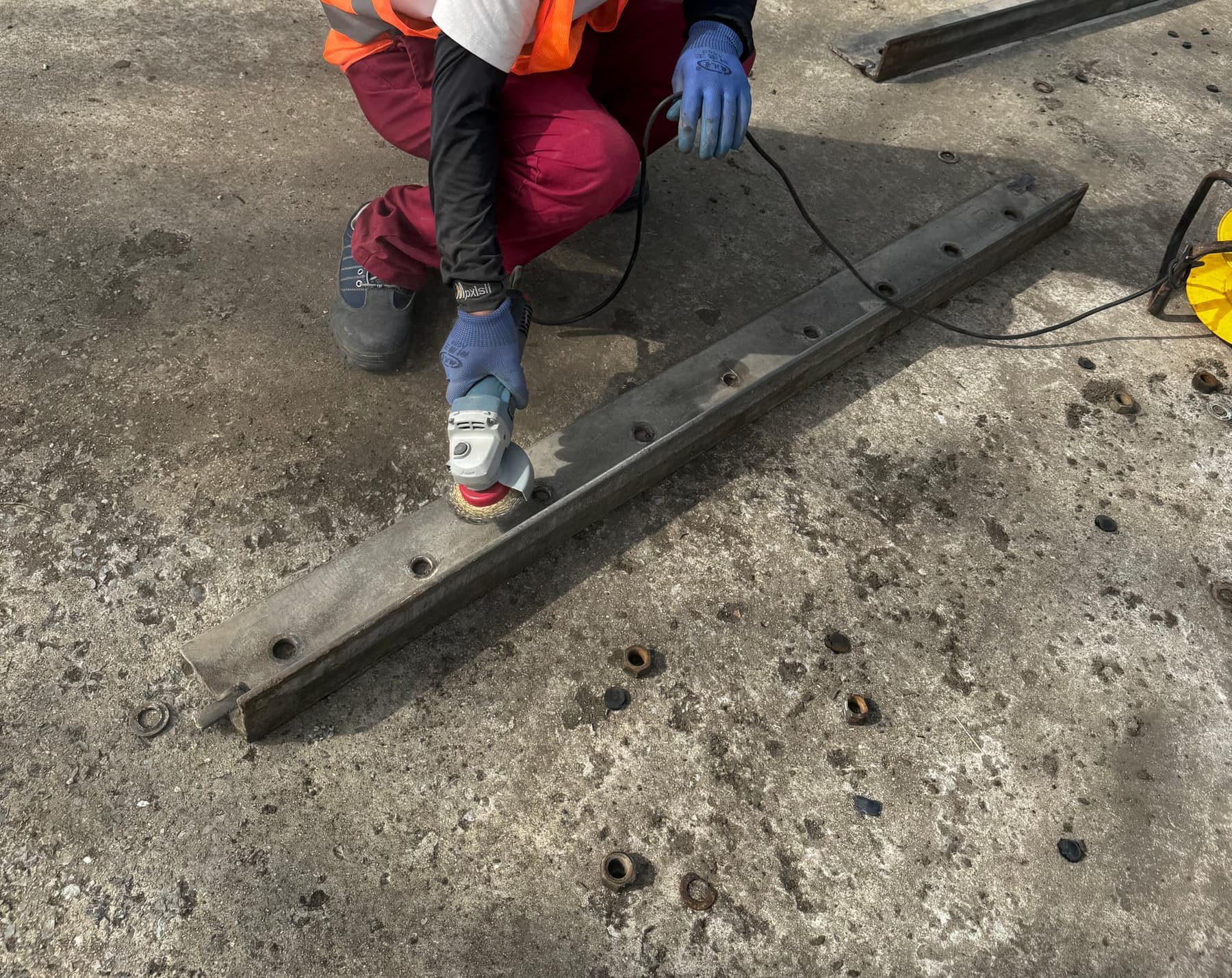
Power-tool cleaning is not performed merely to make the steel look brighter. It removes corrosion, loose material and sharp defects that could weaken coating adhesion or damage the new membrane. Anchor holes, steel edges, welds and former water traps deserve particular attention.
QA hold pointSurface preparation grade, cleanliness, profile and the boundary of retained coating must be accepted against the approved coating specification.
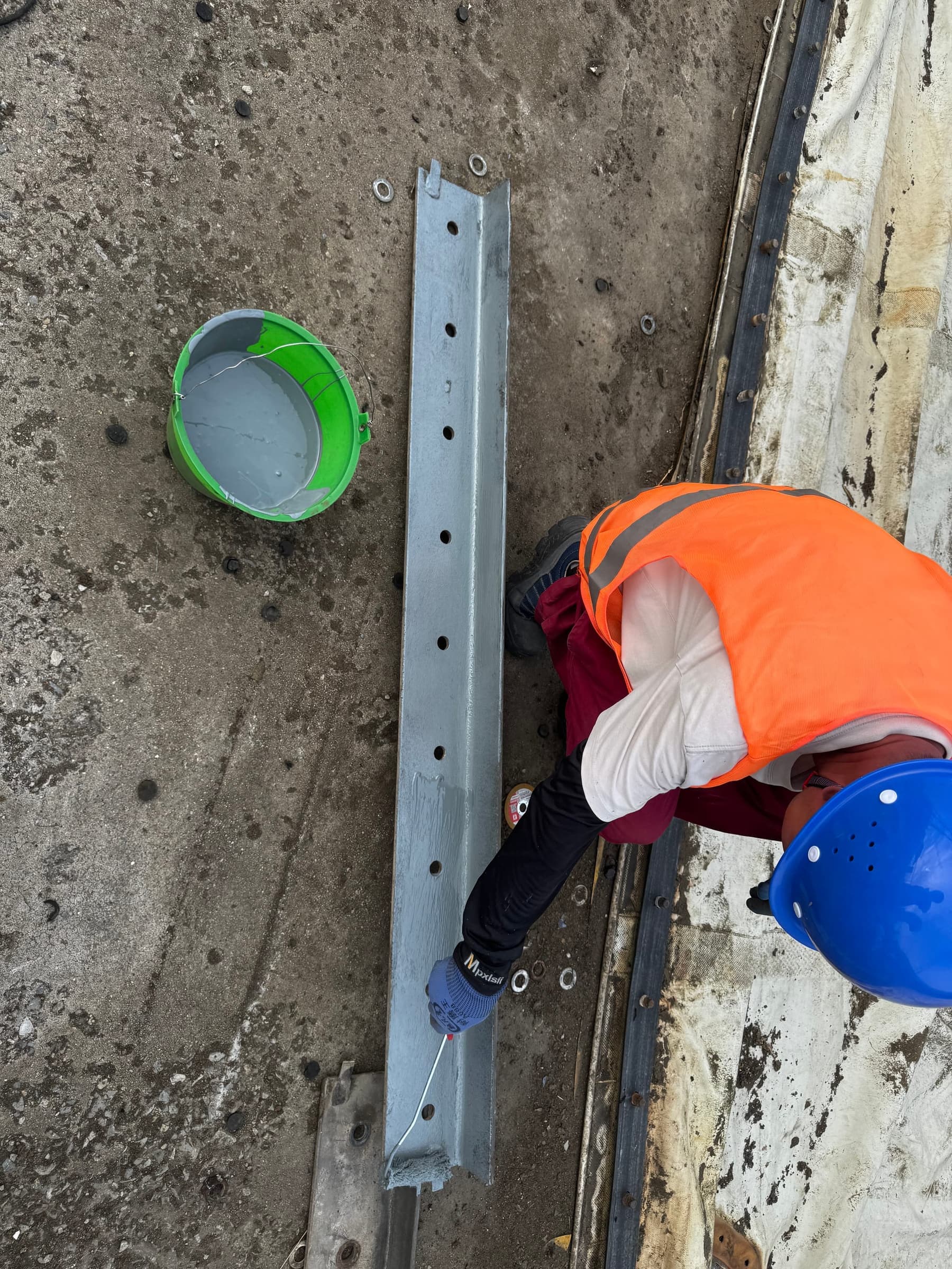
Restore the protective coating and verify cure
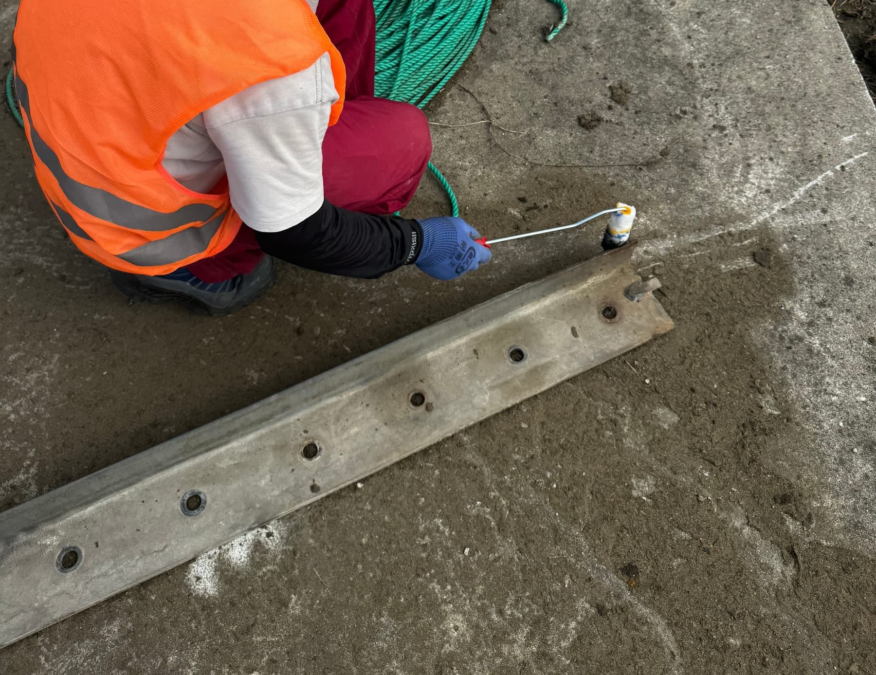
Prepared steel should be coated promptly under the approved system to limit flash rusting. The coating protects the steel and provides a clean, even interface for the sealing strip and membrane edge. The new membrane should not be clamped until the coating has reached the condition permitted for assembly.
QA hold pointRecord ambient conditions, material batch, application time, coat sequence, specified film thickness and recoat/cure status; exact values come from the approved coating system.
6. Sealing System: The Foundation of Reliable Operation
Clean the interface and verify the sealing strip
Before installation, remove dust, abrasive residue, oil, old sealant and hard particles from the clamping faces. The seal should sit continuously around the perimeter without local steps or gaps at joints and changes of direction. Bolts, washers and bars should be checked before clamping begins.
QA hold pointSeal size, continuity, joint location and compression condition must match the approved detail. Hardened, cracked or permanently deformed material must not be assumed reusable.
7–8. Lift, Unfold and Secure the New Outer Membrane
Confirm orientation, lifting points and ground protection
Outer membranes normally arrive folded or packed. Clean ground protection is laid first, followed by approved slings and tag lines. The ground crew controls rotation and swing so the membrane reaches the centre in the intended orientation instead of relying on forced twisting later.
QA hold pointBefore lifting, recheck membrane identification, unfolding direction, fitting orientation and the lifting plan. The membrane must not drag across concrete, exposed anchors or sharp edges.
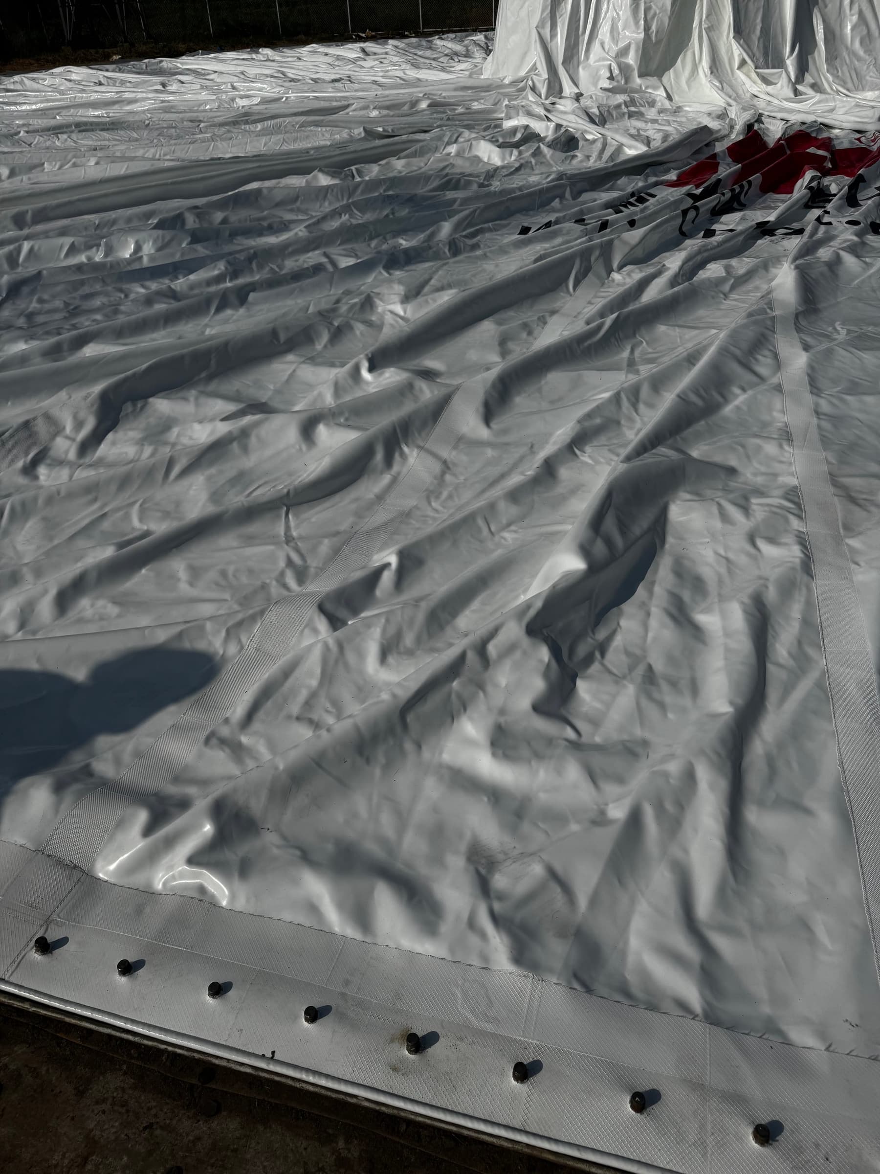
Unfold by sector, establish datums and fasten evenly
After unfolding, the reinforced membrane edge is brought progressively to the perimeter angle and clamping position. The correct approach is not to lock the entire circumference from one starting point. Datum points, opposed sectors and repeated allowance checks reduce concentrated wrinkles, displaced fittings and local over-tension.
Fastening sequence, final torque and permitted membrane tension are supplier- and project-controlled parameters and cannot be inferred from photographs. Calibrated tools and sector-by-sector records should be used.
QA hold pointConfirm centre lines and critical fittings first, then use opposed temporary sectors, recheck allowance and complete clamping in the approved sequence.
9. Reassemble Fittings, Support Air and Controls
Restore every interface—not only the visible membrane
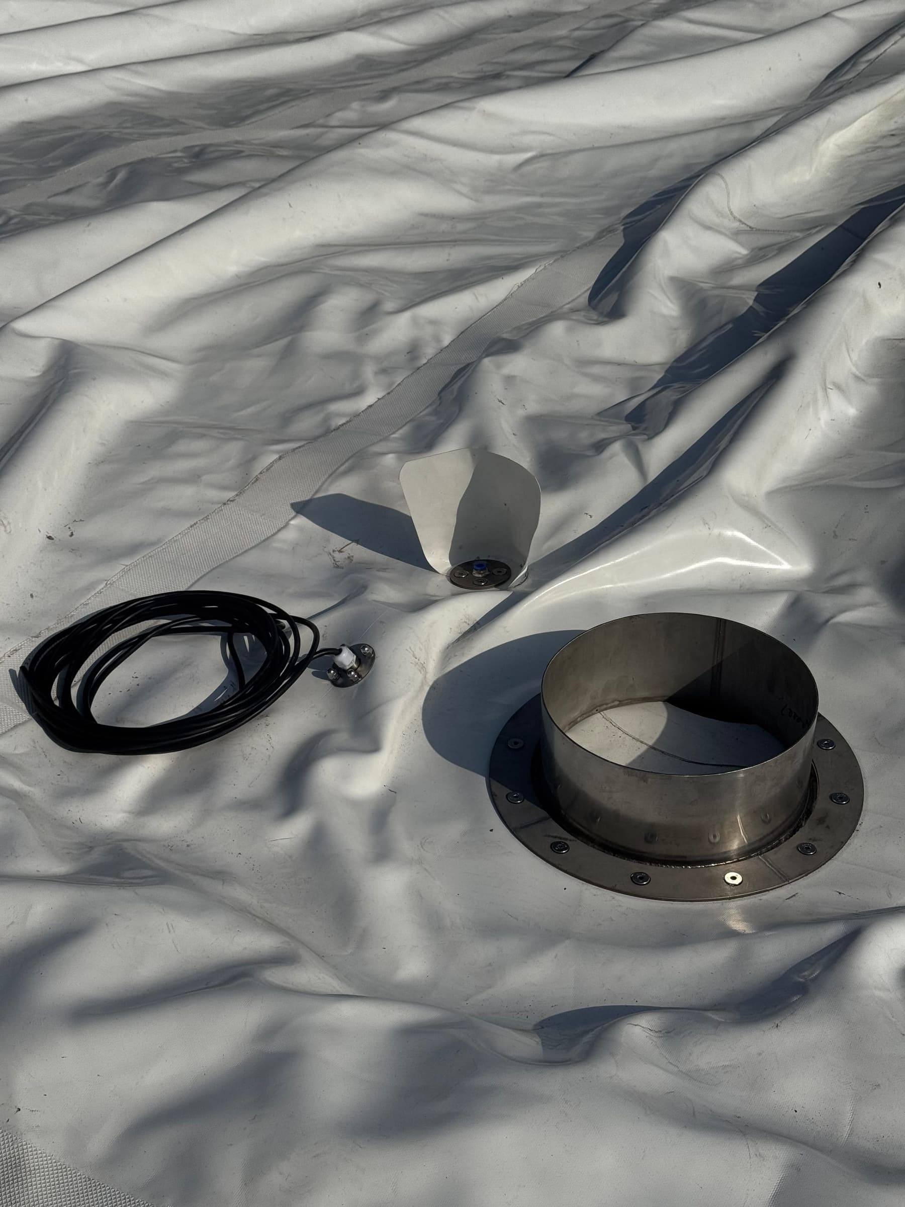
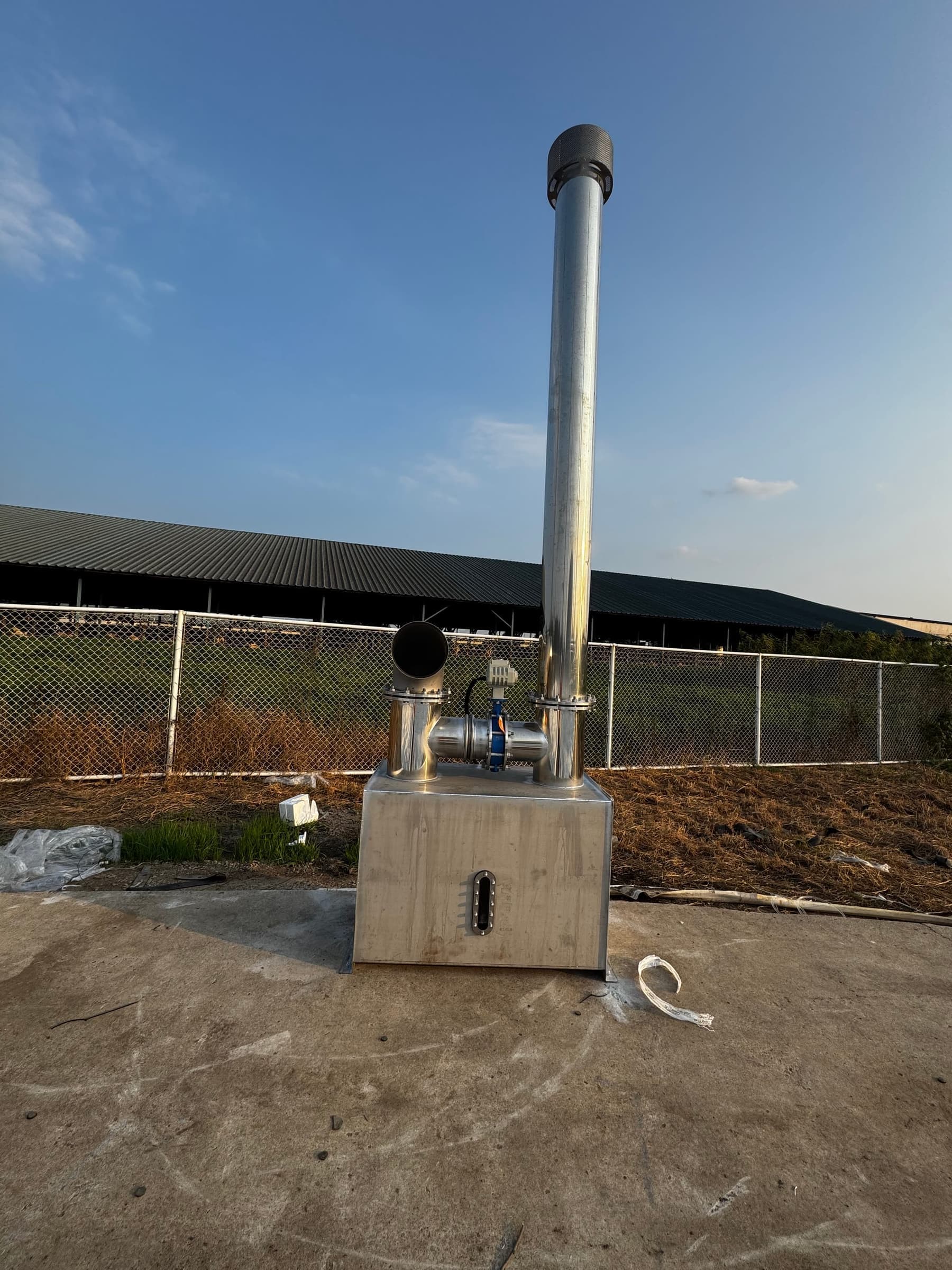
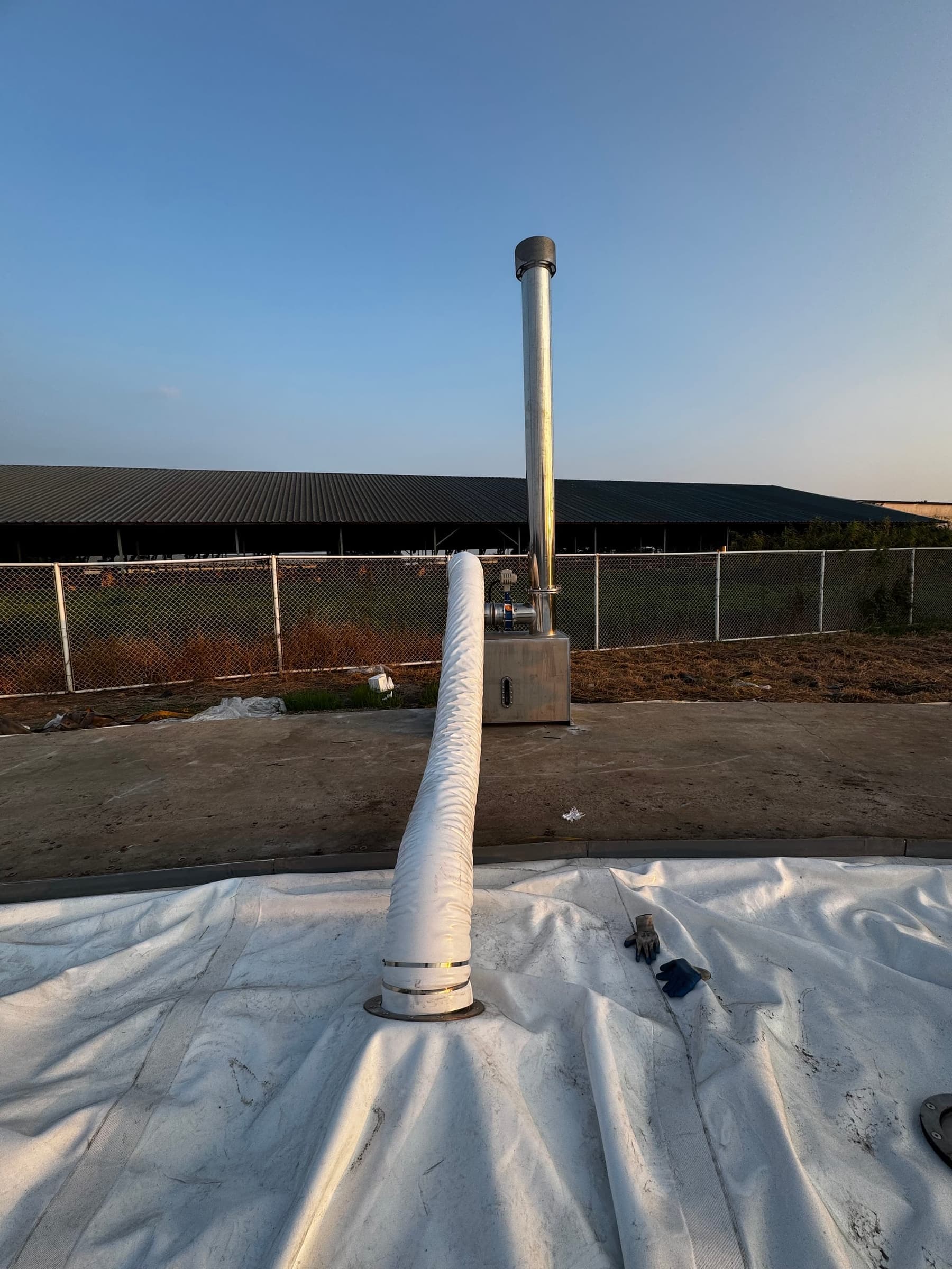
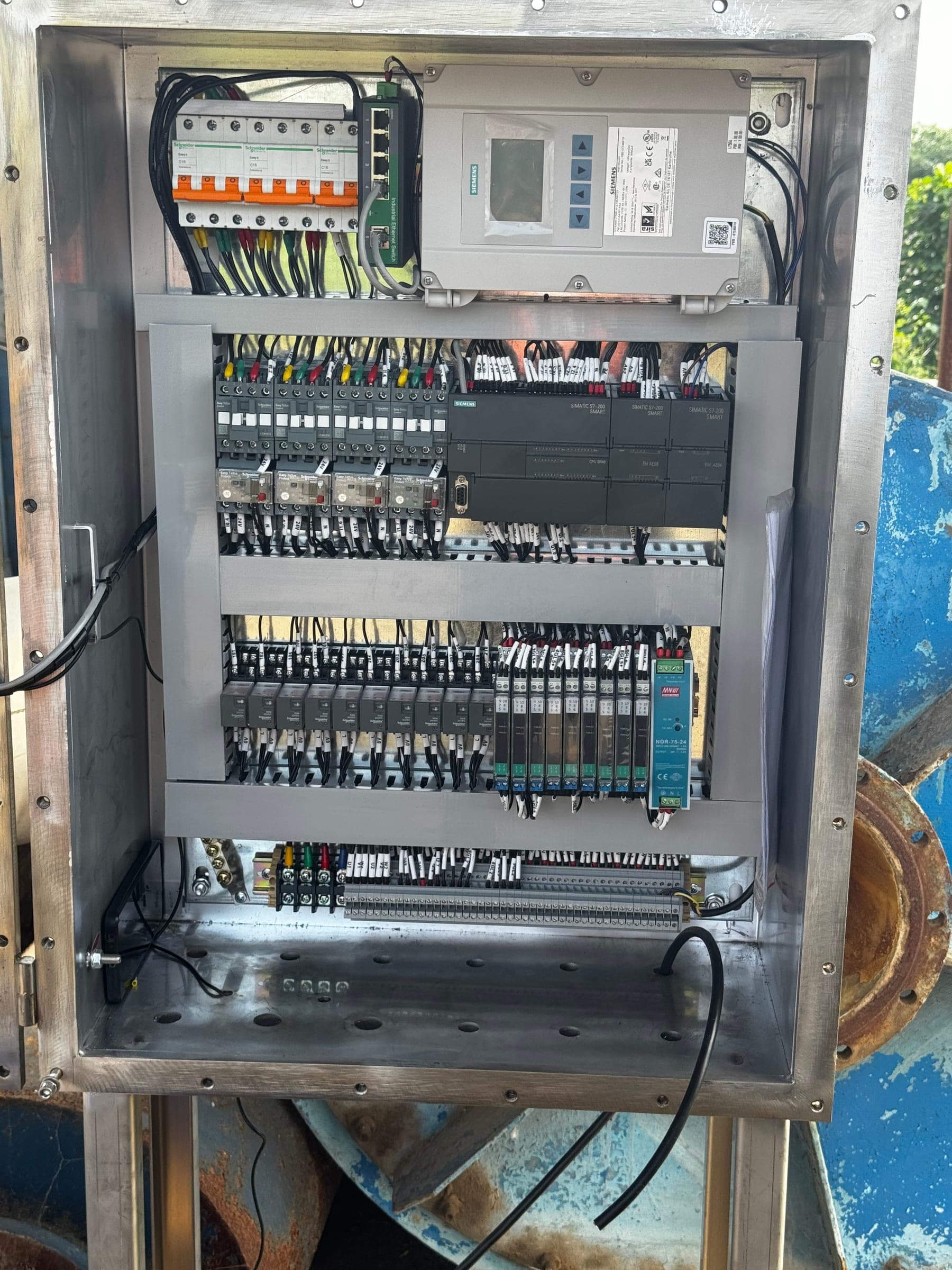
After perimeter fastening, membrane flanges, instrument points, cable seals and flexible connections must be reinstated without twist or unintended load. Support-air equipment establishes and maintains the outer profile, while the control cabinet reconnects pressure, level, alarm and interlock functions into a verifiable system.
QA hold pointUse an interface checklist to confirm membrane flanges, flexible ducts, cables, pressure/level signals, blowers and valves are restored and checked for orientation, sealing and electrical continuity.
10. Controlled Inflation, Functional Testing and Acceptance
Return the system progressively from a low-energy state
During initial support-air inflation, personnel should observe the circumference to confirm that the membrane rises evenly from the centre without snagging, abnormal folding, local stress or movement at the clamped edge. Pressure increase is controlled and cross-checked against field signals.
The project procedure then verifies blower changeover, pressure control, level measurement, alarms, interlocks and upstream/downstream interfaces. Process gas is reintroduced only after membrane profile, sealing, controls and records have been accepted.
QA hold pointDo not enter normal operation until perimeter inspection, interface checks, instrument confirmation, alarm/interlock tests and the approved leak-check sequence are complete.
Common Errors and the Records That Should Be Handed Over
Common errors
- Covering corrosion or sharp edges with the new membrane
- Clamping before the coating is ready for assembly
- Discontinuous seal joints or particles beneath the seal
- Locking the circumference from one point and losing allowance
- Leaving ducts or cables twisted or under load
- Checking appearance without testing alarms and interlocks
Recommended handover records
- Isolation and gas-test records
- Removal inspection and defect photographs
- Steel repair and coating quality records
- Sealing, fastening and sector inspection sheets
- Membrane and fitting installation checks
- Leak, pressure, alarm, interlock and trial-run results
Frequently Asked Questions
When is full outer-membrane replacement preferable to a local patch?
A local repair may be suitable for isolated, repairable damage when the surrounding membrane remains sound. Replacement should be evaluated when ageing, widespread cracking, loss of coating, repeated repairs, dimensional distortion or multiple weak areas make local work unreliable.
Does the outer membrane normally contain biogas?
Normally, no. The inner membrane contains the biogas while the outer membrane forms the weather enclosure and is maintained by support air. The complete system must still be isolated and made safe before membrane work begins.
Why must the clamping steelwork be treated before the new membrane is fitted?
Rust, sharp edges, loose coating and surface contamination can damage the new membrane, reduce sealing reliability and shorten the life of the refurbished assembly. The substrate therefore needs an approved preparation and coating process.
Can the existing sealing strip be reused?
Only after inspection against the approved design. Hardened, permanently compressed, cracked, contaminated or dimensionally unsuitable sealing material should not be assumed reusable.
Why is the membrane fastened progressively around the circumference?
Progressive, balanced fastening helps distribute membrane allowance and clamping load, control alignment and prevent a local section from consuming the adjustment needed elsewhere around the perimeter.
What must be checked before the gas holder returns to service?
Typical checks include membrane alignment and shape, perimeter sealing, penetrations, support-air equipment, pressure and level signals, alarms, interlocks and a controlled inflation or leak-check sequence defined by the supplier and project procedure.
Technical basis and limits
Terminology for steel-surface cleanliness may be referenced to ISO 8501-1, while the EPA AgSTAR guide provides broader biogas O&M and hazardous-energy context. This article explains an engineering workflow; it is not a site-specific method statement, risk assessment or commissioning procedure. Local regulations, supplier documentation and the approved project plan govern the work.
Related MOTET Products
Maintenance & Retrofit Inquiry
A replacement plan should begin with inspection of the existing system—not with a membrane quotation.
Send MOTET the gas holder dimensions, drawings, membrane data, operating pressure, defect photographs and available shutdown window. Our engineering team can assess the repair-versus-replacement boundary, site work conditions, interface modifications and return-to-service plan.
Contact our engineering team