MOTET / System components and operation
Published September 6, 2026 · Updated October 7, 2026
What Is a Double Membrane Gas Holder?
A double membrane gas holder, also written double membrane gasholder, is a low-pressure, variable-volume membrane storage system. It buffers the mismatch between gas production and consumption. It is neither a high-pressure compressed-gas vessel nor simply a bag made from two sheets: the gas-tight boundary, support air, instruments, protection and site interfaces form one engineered system.
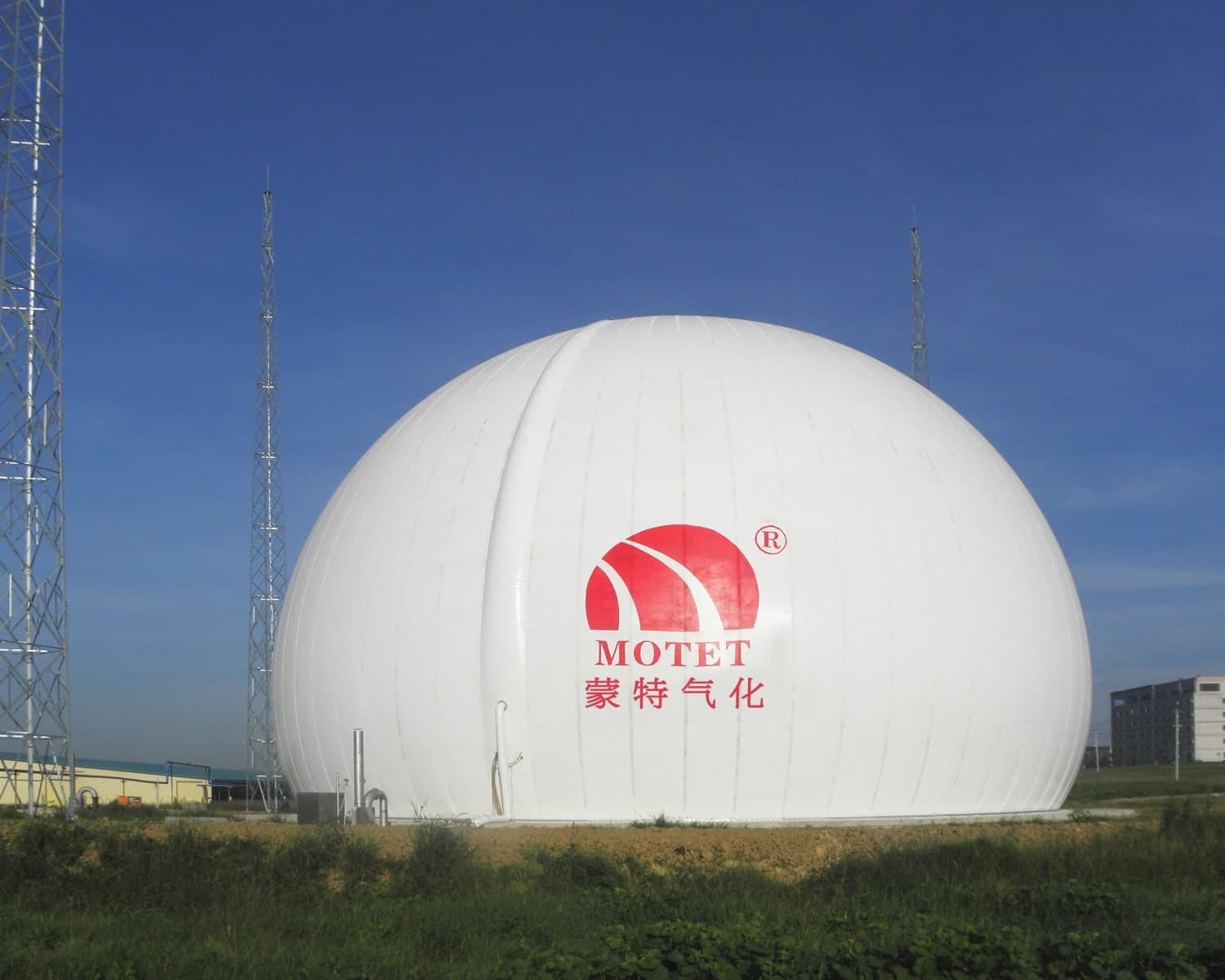
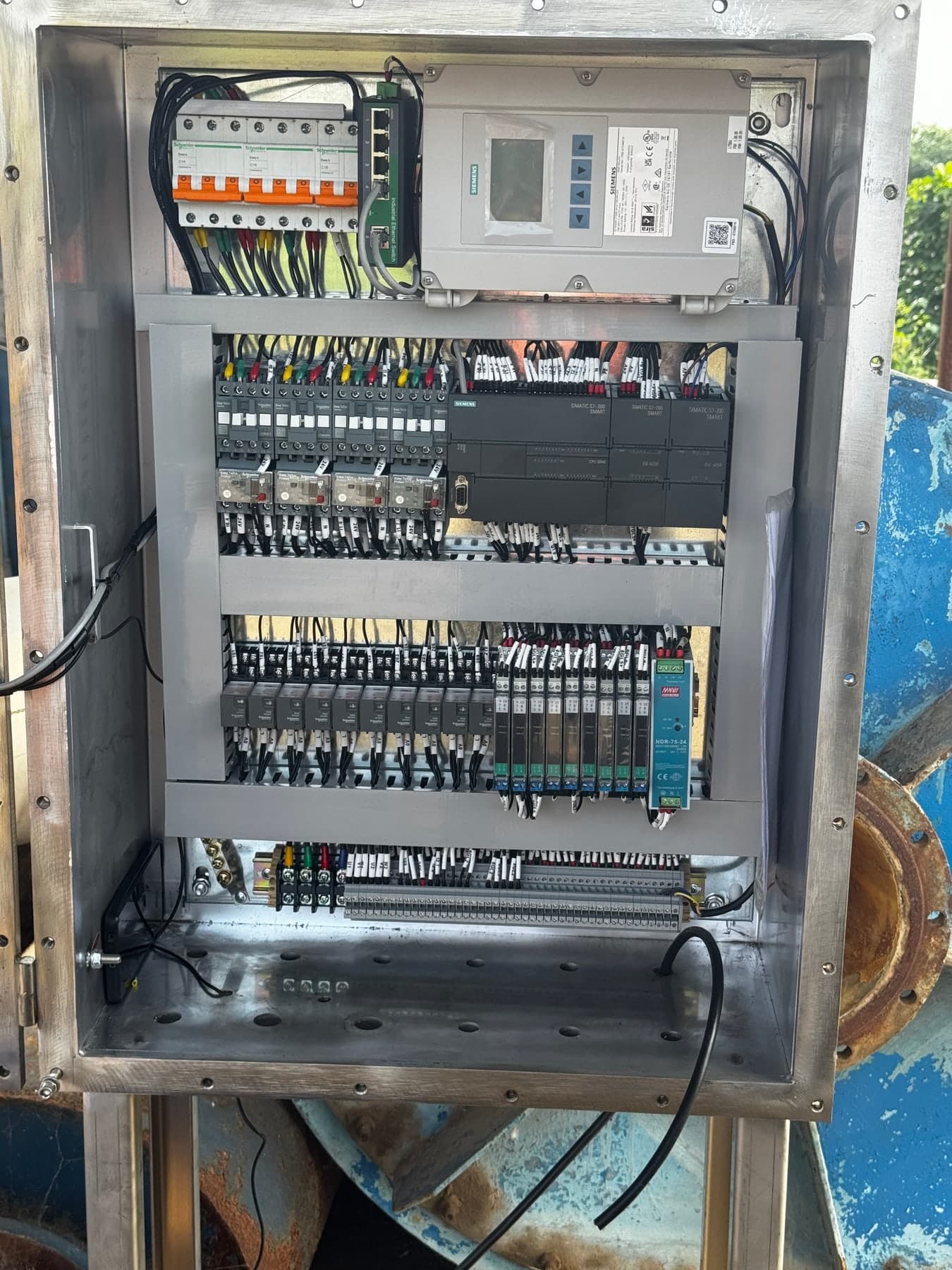
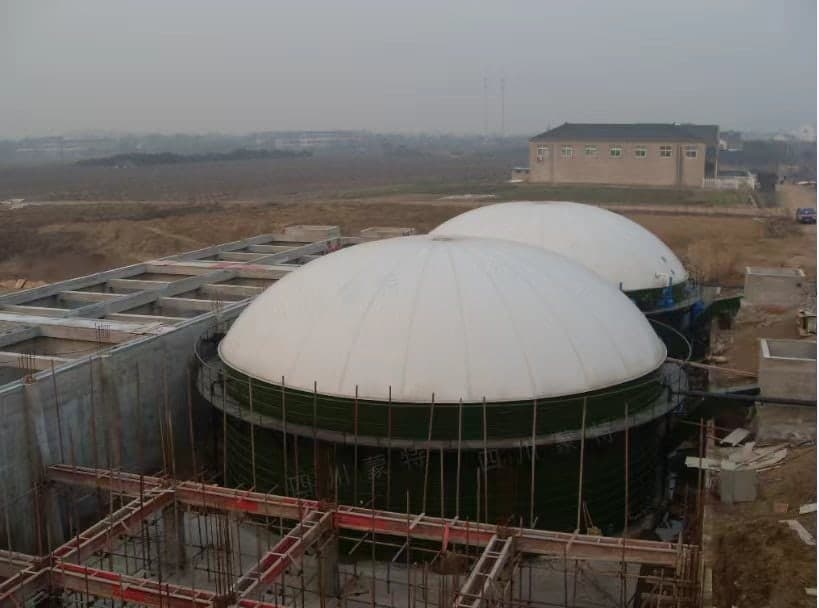
The photographs connect project appearance, membrane installation, a pressure transmitter and a control cabinet to their functions. They represent different projects or installation stages, not a verified bill of materials for one installation. Photographs alone do not establish capacity, pressure, certification or acceptance.
How Is It Different from a Traditional Gasholder?
Gas holder and gasholder are alternative spellings, not names for modern and traditional machines respectively. The distinction is structural: a wet holder has a water seal and moving bell; a conventional dry-seal holder has a fixed shell, moving piston and perimeter seal. A double-membrane holder changes gas volume through a flexible inner membrane, with support air maintaining the outer enclosure rather than a moving steel bell or large piston.
Waterless does not mean identical to a conventional dry-seal piston holder. A Wiggins-type holder can also use a flexible sealing curtain, but that curtain seals around a piston; it is not the gas chamber of a double-membrane biogas holder. Selection and maintenance must follow the actual containment and load-bearing arrangement.
Structural references: Historic England · Wiggins patent
Read the Gas Holder overview: wet, dry and membrane typesMain Components of a Double Membrane Gas Holder
Think in three connected layers: containment comprises the inner membrane, base or tank, gas pipes and sealed joints; support comprises the outer membrane, air blowers, ducts, non-return and regulating devices; monitoring and protection comprise pressure and level measurement, the control cabinet, alarms, interlocks and independent protective devices. The actual scope must agree with approved arrangement drawings, P&IDs and the control philosophy.
Double membrane usually names the inner and outer upper membranes; it does not mean that the entire installation contains only two membrane pieces. A floor-standing system may include a bottom membrane. A tank-top system uses the tank and its interfaces for the lower boundary, with membrane support as specified. Base and support details are not interchangeable between configurations.
Inner Membrane: the Variable-Volume Gas Boundary
The inner membrane separates stored gas from support air and moves with the gas inventory. Gas tightness depends on seams, reinforced areas, perimeter seals and penetrations as well as the fabric itself. Material selection must address gas composition, moisture, temperature, corrosive constituents and permeability, not merely fabric weight or colour.
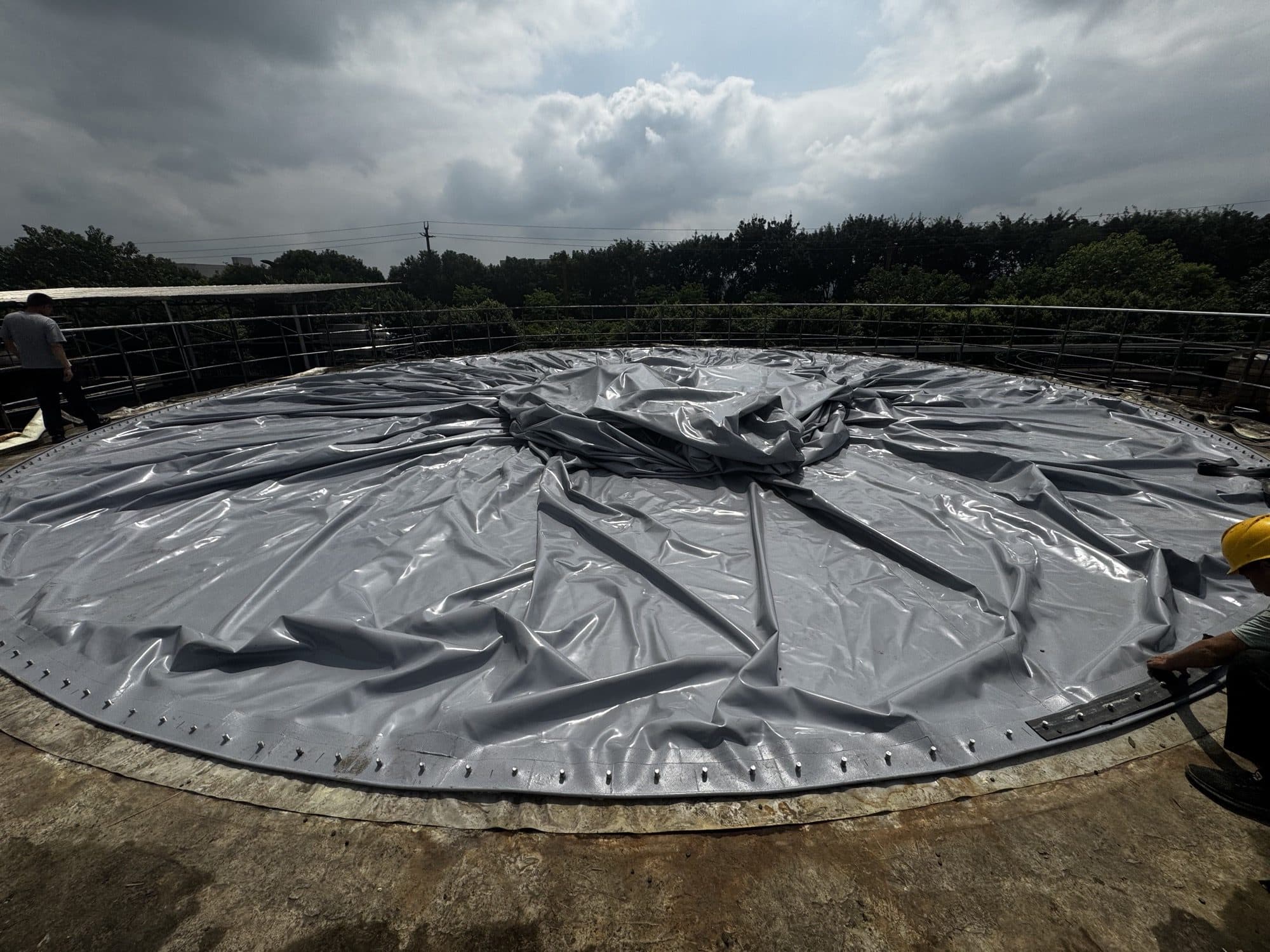
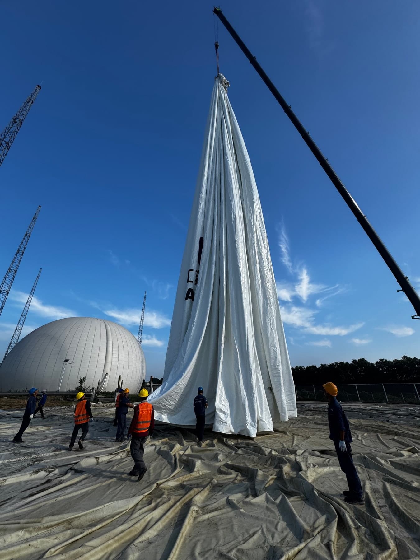
Installation photographs can show unfolding and perimeter connections, but cannot prove seam strength or a passed leak test. Handover records should link material traceability, welding procedures and quality records, interface checks and the specified leak-test results. Inner-membrane replacement also requires compatibility checks with retained outer membranes, clamps and instrument interfaces.
Outer Membrane: Enclosure, Shape and Perimeter Restraint
The outer membrane forms the visible enclosure, resists weather actions within its design scope and is held in shape by support air. The space between membranes is not normally a biogas storage chamber. Wind, snow, UV exposure, temperature, anchoring and drainage still matter: not directly containing biogas does not justify lower manufacturing quality.
Lifting and spreading must protect seams and reinforced edges from dragging and concentrated loads. Clamp plates, sealing strips, fasteners and the substrate form a continuous joint. Seal material, joints and compression must follow the interface design; ad-hoc sealant is not a substitute for the specified clamped seal. Fastening sequence and torque come from approved documents.
Support Air and Pressure Control: Keep the Two Fluid Paths Distinct
Support blowers supply air between the membranes; air-release or regulating devices accommodate changes in gas-chamber volume. Gas inlet and outlet pipes connect to containment, while blower ducts connect to the support-air space. A support blower is not a biogas booster, and its air supply must not be routed into the biogas chamber.
Gas-side and support-air pressures are related, but their measurement points and settings are not interchangeable. Design must define blower redundancy, non-return devices, regulation, power-loss conditions and loss-of-support-air response. Normal regulation, alarm/interlock actions and independent pressure protection must be coordinated; a pressure sensor cannot itself relieve pressure.
Operating-principle reference: Utile / Ceno-Tec, Principle of Operation (another manufacturer’s literature, not a MOTET specification or certification statement).
Pressure Transmitters, Level Measurement and the Control Cabinet
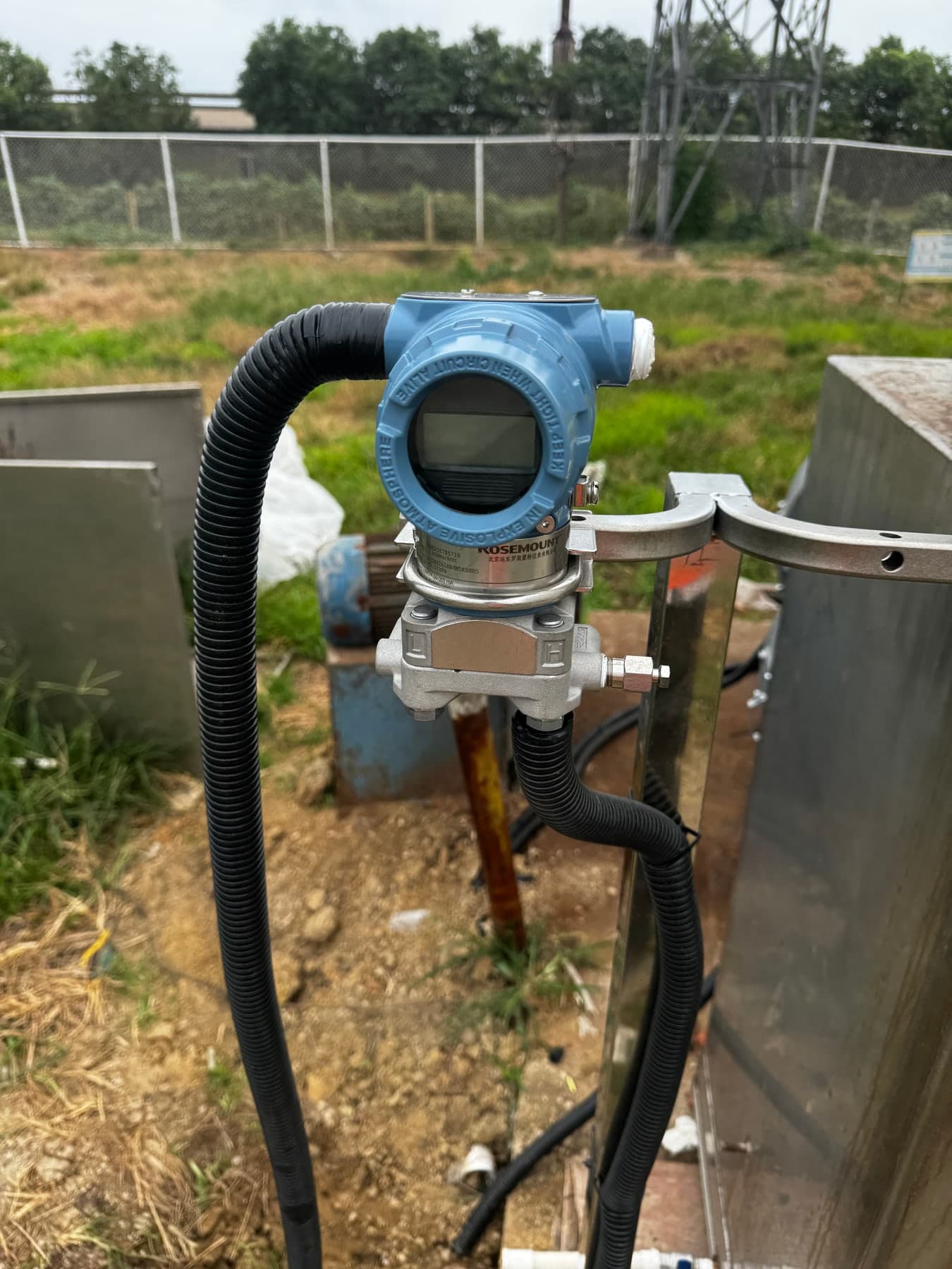
A pressure sensor detects pressure; a transmitter provides a defined electrical signal to the control system, often with sensing integrated in the same device. Check range, pressure reference, tapping location, media compatibility, condensate effects, calibration and signal-failure handling. A visible brand or enclosure does not establish measurement range, hazardous-area suitability or certification of the complete system.
Level or membrane-position measurement indicates filling condition; pressure measurement indicates whether pressure is within its allowed range. Different inventories may have similar pressures under normal regulation, so pressure is not a direct volume reading. Ultrasonic or other position instruments require defined mounting references, dead zones, obstruction and reflection checks, and a validated position-to-usable-volume relationship.
The cabinet receives signals and executes the approved control logic. It may contain power and protection devices, PLC, I/O, relays, signal isolation and communications. The photograph illustrates wiring and layout, not a standard brand or program required in every holder. Commissioning must verify terminals, wire identification, grounding, loop direction, blower/valve actions, alarms, interlocks and fault scenarios.
From Components to a Complete System: Gas, Air and Signal Paths
A system cannot be accepted merely by counting membranes, a blower and a cabinet. Verify a continuous gas-tight containment boundary; then establish correct separation and operation of the support-air system; finally prove that each measurement, control action and independent protection corresponds to the physical installation. Drawings, interface lists, cause-and-effect documentation and site checks must agree.
Mechanical checks address membrane edges, sealing strips, clamps, flanges, hoses and penetrations. Electrical checks address cable-entry seals, grounding, loop tests and local hazardous-area requirements. Leak testing, controlled inflation, level/pressure checks and alarm/interlock tests serve different purposes. An inflated outer membrane or a cabinet photograph cannot substitute for complete acceptance.
Gas path: production → inlet interface → inner-membrane gas chamber → outlet interface → consumer / flare
Air path: support blower → duct and non-return device → inter-membrane air space → regulation / air release
Signal path: pressure / level instruments → cabinet → approved control, alarm and interlock actions; verify independent protection separately
Gas Storage and Discharge: High and Low Filling Conditions
When inlet flow exceeds outlet flow, inventory increases and the inner membrane tends to rise; when outlet flow exceeds inlet flow, it falls. The support-air system responds to the changing gas space. A maintained outer shape does not mean the gas chamber is full; low level does not mean gas-free or safe to enter or work on.
High-level actions may adjust gas use or prepare the flare, while low-level actions may protect consumers from inadequate supply. The response is not universal: coordinate it with digestion, flare, consumers and network control boundaries. Maintenance requires shutdown, isolation, purging and testing under a project-specific procedure performed by qualified personnel.
Operation and maintenance reference: EPA AgSTAR — Operator Guidebook
Floor-Standing vs Tank-Top: Define Installation Boundaries
Floor-standing storage can be independent of the digester, with foundation, lower containment, footprint, drainage and pipework checks. Tank-top storage uses space above a tank but requires verification of the tank wall, perimeter support, interface geometry, anchoring and internal support. Tank diameter alone is not a sufficient membrane or structural specification.
Sizing, Quality Handover and After-Sales Scope
Capacity follows time-dependent production and consumption, outage strategy and required operating reserve. Usable gas volume is not the apparent outer-envelope volume. Compare pricing on equal material, climate-load, instrumentation, blower-redundancy, valve, control, transport and installation scope. There is no universal torque, pressure, membrane thickness or service-life promise in this article; approved project documents govern the values.
Worked example—assumed duty, not project data: production of 100 m³/h and consumption of 60 m³/h for 3 h add (100 − 60) × 3 = 120 m³ to inventory, assuming a common volume basis and no other inflows or outflows. This is an inventory increase, not a recommendation to buy a nominal 120 m³ holder. Check starting inventory, permitted high/low levels, operating reserve and the later consumption period. Accumulate net flows over the complete operating cycle to check inventory peaks, troughs and shutdown scenarios; gas beyond the usable limit needs the approved control and disposal arrangement.
Agree the volume basis first. Gas volume in m³ at operating conditions is not automatically equal to normalised volume in Nm³. State the reference temperature, absolute pressure and dry/wet basis, and use the same basis for flow data; gauge pressure is not absolute pressure. A quotation should distinguish geometric volume, usable inventory between specified high and low gas levels, and operating reserve—not treat the outer envelope as available storage.
Make acceptance traceable for the next operator: record the equipment ID, drawing revision, test date, inspected boundaries, approved test medium/pressure/hold time/pass criteria, results and closure of defects. Keep calibration, membrane-position-to-volume mapping, loop checks and interlock tests as separate records. One leak check or cabinet photograph is not verification of protective devices or proof against leakage under every operating condition. For service support, supply the equipment ID, pressure/level trends, alarm times and interface photographs; do not bypass protection to troubleshoot.
MOTET can help configure equipment for the duty, with interface review, installation guidance, commissioning, training, remote support, spares and membrane replacement within the agreed contract scope. After-sales support requires more than a phone number: hand over drawing revisions, membrane and seam records, calibration, interlock tests, maintenance guidance and spare-parts boundaries. Specify service territory, response arrangements and warranty during procurement.
Volume-basis reference: Endress+Hauser — Proline Prowirl 200, General principles, §4.2 (pp. 14–16)

Review the Duty and System Scope with Our Engineering Team
Provide gas composition, production/consumption profiles, usable-volume target, pressure, site, installation type and supply boundaries for a technically comparable proposal.
Frequently Asked Questions
Is a double membrane gasholder the same as a traditional gasholder?
It belongs to the broader gas-holder family, but its flexible inner gas membrane and support-air enclosure differ from the moving bell of a wet holder and the piston of a conventional dry-seal holder. Gasholder and gas holder are alternative spellings, not separate equipment types.
Can pressure alone tell us the stored gas volume?
No. Under normal pressure regulation, different inventories may have similar pressure. Level or membrane-position measurement and the specified calibration relationship are needed to estimate usable gas volume.
Does the outer membrane store biogas?
Normally, no. The inner membrane separates the biogas storage chamber from the support-air chamber, while the outer membrane forms the external enclosure.
Why is air supplied between the two membranes?
Support air maintains the external membrane shape and forms part of the pressure-control arrangement.
Does a double membrane gas holder compress biogas?
Not in the same sense as a high-pressure compressor or compressed-gas vessel. It is primarily a variable-volume, low-pressure storage and buffering system.
Can it store gases other than biogas?
Potentially, but membrane material, permeability, chemical compatibility, hazardous-area requirements and safety design must be evaluated for the specific gas composition and project conditions.
How long should biogas be stored?
There is no universal storage time. Capacity should be calculated from the actual mismatch between production and consumption and the operating strategy of the plant.
Which is better: tank-top or floor-standing?
Neither is universally better. Tank-top systems can save plot area, while floor-standing units provide independent storage and greater layout flexibility.
References and scope
- Wikipedia — Gas holder (background reading)
- Historic England — Gasworks and Gasholders
- US2583981A — Dry seal pressure type gasholder
- Utile / Ceno-Tec — Double Membrane Gas Holders, Principle of Operation
- EPA AgSTAR — Anaerobic Digester/Biogas System Operator Guidebook
- Endress+Hauser — Proline Prowirl 200, General principles, §4.2 (pp. 14–16)
Wikipedia is background reading for terminology and history; structural distinctions are checked against engineering references. Equipment and project photographs are captioned with their installation stage and scope. This guide does not replace project design, method statements, hazardous-area assessment or local rules.